Product Recognition | |
|---|
Certification Number | ZC14-22050108 |
|---|
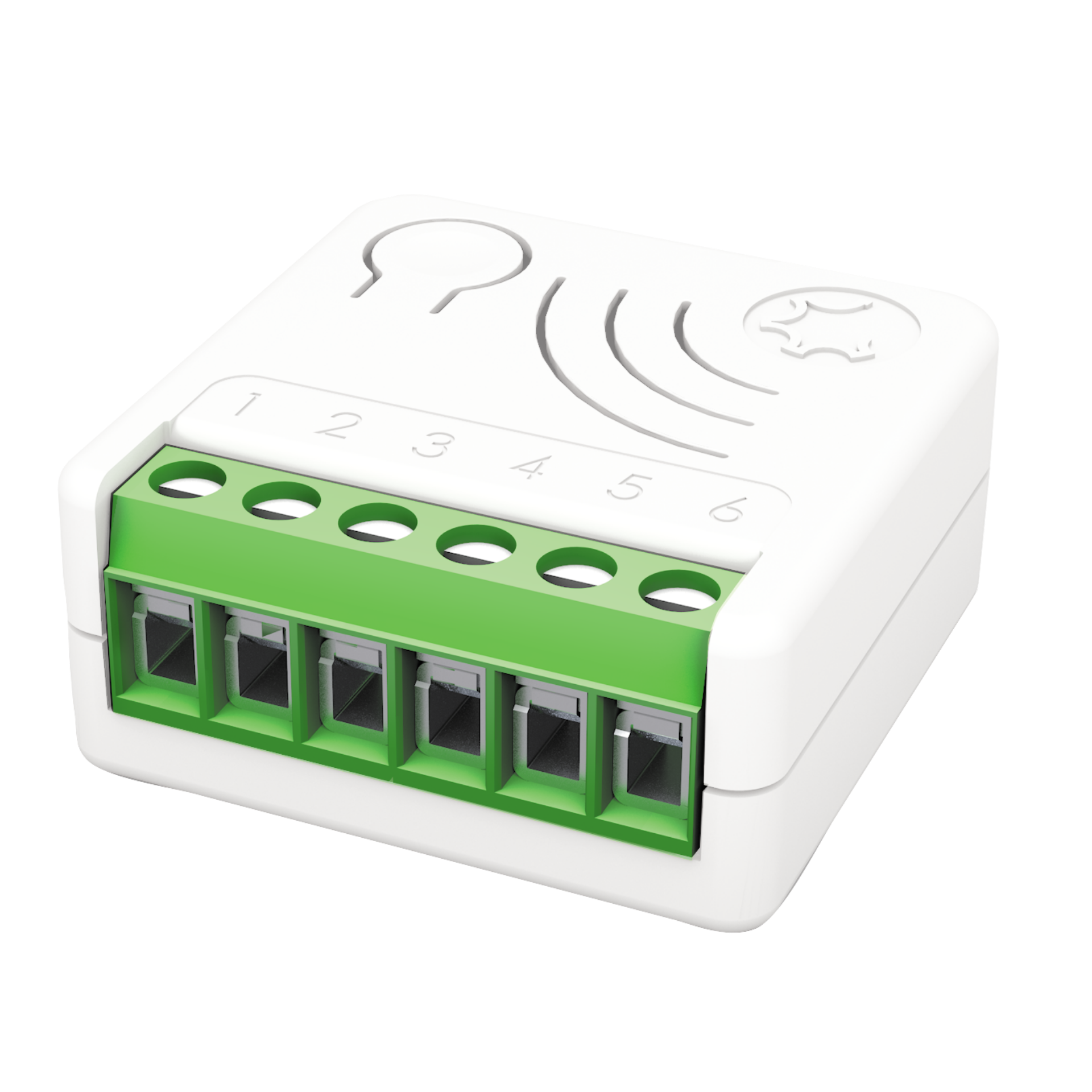
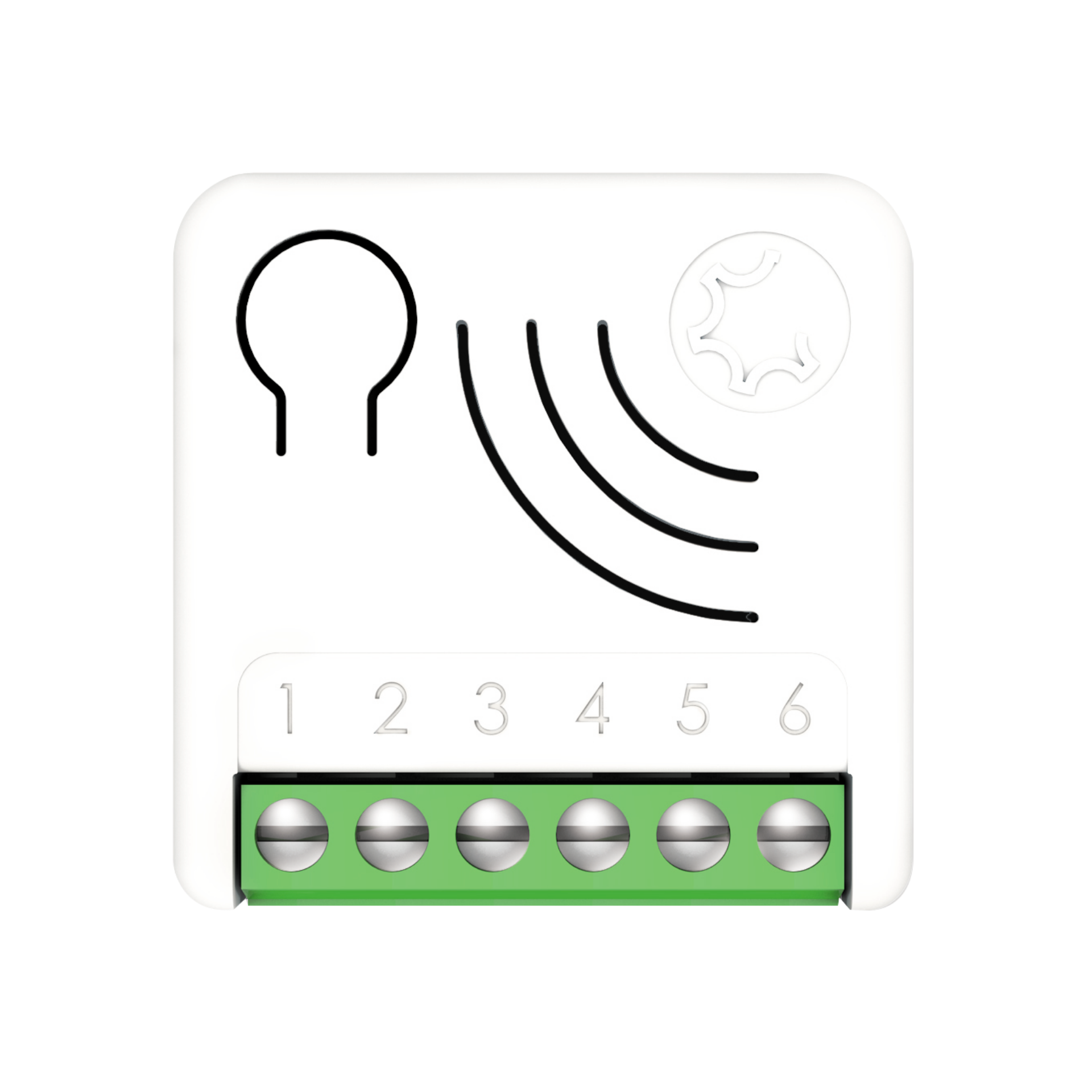
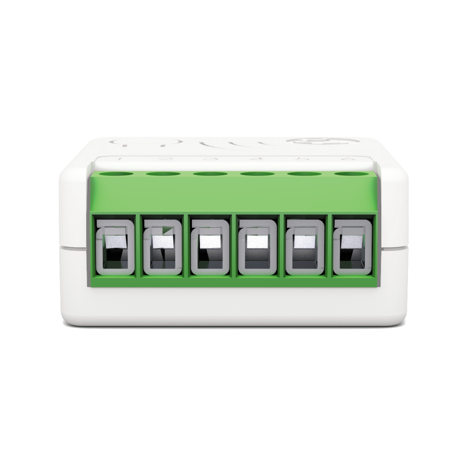
Name | META DRY CONTACT SWITCH ZRX |
|---|
Short Description | META Dry Contact Switch 7 can turn ON and OFF equipment’s with an independent power supply, such as solenoid valves (e.g. gas, water and irrigation), power operated valves etc.
In its ZRX variant the device can also be controlled by Cherubini Remote Controls of SKIPPER - POP OR GIRO series. |
|---|
Long Description | Turns ON and OFF the load by using an external switch, or from remote through a controller.
Works with both momentary and toggle switches.
In its ZRX variant the device can also be controlled by Cherubini Remote Controls of SKIPPER - POP OR GIRO series.
16 Amp relay.
The unique feature Offline Setup Mode allows to configure some parameters without using any user interface. This feature enables the professional user to setup the main features of the device in the field even if the device is not included in a Z-Wave ™ Network. When the device will be included in the network all these configuration parameters will be maintained
A timer can be set when switching On and/or Off. It is also possible to define which event will start the timer.
The device supports Central Scene Notification, and the events that trigger the Report can be customized with the configuration parameters.
As a constantly powered node, the device will act as repeater in order to increase the reliability of the network.
This device is a security enabled Z-Wave Plus ™ product
The system supports over-the-air firmware updates that do not require the device to be removed from its location.
The system includes an RGB LED indicator that shows the device’s status during installation
Power supply: 110 - 230 VAC±10% 50/60 Hz - 24VDC
Maximum Load on Relay: 16A resistive Load
The extremely small size facilitates installation: 37x37x17 mm
Maximum distance: Up to 100 m outdoor - Up to 40 m indoor
New Z-Wave™ serie 700, SmartStart and S2 security |
|---|
Brand | Cherubini |
|---|
Product Identifier | A510088 |
|---|
Product Line | Z-Wave Product |
|---|
OEM Version | HW: 01 FW: 07.00 |
|---|
Hardware Platform | ZGM130S037HGN2 / ZGM130S037HGN1 |
|---|
Z-Wave Version | 7.16.3 |
|---|
Library Type | END_NODE_ENHANCED_232 |
|---|
Device Type | Binary Switch DT |
|---|
Role Type | ROLE_TYPE_SLAVE_ALWAYS_ON |
|---|
Manufacturer ID | 0x0149 |
|---|
Product Type ID | 0x0004 |
|---|
Product ID | 0x0007 |
|---|
User Icon | 0x0700 |
|---|
Installer Icon | 0x0700 |
|---|
Frequency Plans | EU: 869.85MHz, 868.40MHz |
|---|
Categories | All Lighting Devices, Water Valves & Irrigation, On/Off Switches/Devices, Gas Valves |
|---|
Countries / Regions | European Union |
|---|
Supported Command Classes | Identifier | Name | Key | Version |
|---|
COMMAND_CLASS_BASIC_V2 | Basic V2 | 0x20 | 2 | COMMAND_CLASS_SWITCH_BINARY_V2 | Binary Switch V2 | 0x25 | 2 | COMMAND_CLASS_CENTRAL_SCENE_V3 | Central Scene V3 | 0x5B | 3 | COMMAND_CLASS_CONFIGURATION_V4 | Configuration V4 | 0x70 | 4 | COMMAND_CLASS_APPLICATION_STATUS | Application Status | 0x22 | 1 | COMMAND_CLASS_ASSOCIATION_V2 | Association V2 | 0x85 | 2 | COMMAND_CLASS_ASSOCIATION_GRP_INFO_V3 | Association Group Information (AGI) V3 | 0x59 | 3 | COMMAND_CLASS_DEVICE_RESET_LOCALLY | Device Reset Locally | 0x5A | 1 | COMMAND_CLASS_FIRMWARE_UPDATE_MD_V5 | Firmware Update Meta Data V5 | 0x7A | 5 | COMMAND_CLASS_INDICATOR_V3 | Indicator V3 | 0x87 | 3 | COMMAND_CLASS_MANUFACTURER_SPECIFIC_V2 | Manufacturer Specific V2 | 0x72 | 2 | COMMAND_CLASS_MULTI_CHANNEL_ASSOCIATION_V3 | Multi Channel Association V3 | 0x8E | 3 | COMMAND_CLASS_VERSION_V3 | Version V3 | 0x86 | 3 | COMMAND_CLASS_ZWAVEPLUS_INFO_V2 | Z-Wave Plus Info V2 | 0x5E | 2 | COMMAND_CLASS_SECURITY_2 | Security 2 | 0x9F | 1 | COMMAND_CLASS_SUPERVISION | Supervision | 0x6C | 1 | COMMAND_CLASS_TRANSPORT_SERVICE_V2 | Transport Service V2 | 0x55 | 2 | COMMAND_CLASS_POWERLEVEL | Powerlevel | 0x73 | 1 |
|
|---|
S2 Classes | S2_AUTHENTICATED, S2_UNAUTHENTICATED |
|---|
Documents | Category | File |
|---|
Manual_English | |
|
|---|
Association Groups | Group Number | Maximum Nodes Supported | End Point ID | Group Name | Profile |
|---|
1 | 8 | 0 | Lifeline | 0x0001 | 2 | 8 | 0 | Follow me | 0x2000 | 3 | 8 | 0 | Clicks on button 1 G1 | 0x200b | 4 | 8 | 0 | Clicks on button 1 G2 | 0x200c | 5 | 8 | 0 | Dimming Group | 0x2002 |
|
|---|
Configuration Parameters | Parameter Number | Name | Description | Format | Size | Min Value | Max Value | Default Value |
|---|
1 | IN_TYPE | Define the input type. (1: button, 2: toggle switch, 0: no switch input) | 2 | 1 | 0 | 0 | 0x01 | 10 | IN_TOGGLE | Define which event on the input toggle output. (1: 1 click , 2: 2 clicks, 4: 3 clicks, 8: Hold down, 16: Up) | 3 | 1 | 0 | 0 | 0x0f | 11 | IN_ON_EXCLUSION | Define which input event do not switchOn output. (0: none, 1: 1 click , 2: 2 clicks, 4: 3 clicks, 8: Hold down, 16: Up) | 3 | 1 | 0 | 0 | 0x00 | 23 | STARTUP_OUT | Define the output level on startup (0: OFF, 1: ON, 2: Previous status, 3: equal to input) | 2 | 1 | 0 | 0 | 0x02 | 31 | OFF_TIMEOUT | Time in tenth of second after which the output will be switched Off. 0: Off timer disabled | 1 | 4 | 0 | 0 | 0x00000000 | 41 | G2_SETUP | Define which input event controls G2 group. (0:none, 1: 1 click , 2: 2 clicks, 4: 3 clicks, 8: Hold down, 16: Up) | 3 | 1 | 0 | 0 | 0x02 | 44 | G1_ASS_VALUE | The value used to control G1 association group. (0-99: specific value, 100: ON, 101: propagate, 102: toggle remote) | 1 | 1 | 0 | 0 | 0x65 | 45 | G2_ASS_VALUE | The value used to control G2 association group. (0-99: specific value, 100: ON, 101: propagate, 102: toggle remote) | 1 | 1 | 0 | 0 | 0x65 | 50 | DIMMING_TIME | Fade On/Off time in second used to control device in dimming group. | 1 | 2 | 0 | 0 | 0x0005 | 51 | MIN_DIM_LEVEL | Define the minimum dimming level to control device in dimming group. | 1 | 1 | 0 | 0 | 0x01 | 60 | SCENE_SETUP | Define event sent by central scene notification. (0:none, 1:1 click , 2:2 clicks, 4:3 clicks, 8: Hold down, 16: Up) | 3 | 1 | 0 | 0 | 0x1f |
|
|---|
Texts | ID | Description | Value |
|---|
8 | Where to find S2 DSK on product | When adding META Serie 7 devices to a Z-Wave network with a controller supporting Security 2 Authenticated (S2), the PIN code of the Z-Wave Device Specific Key (DSK) is required. The unique DSK code is printed on the product label. The first five digits of the key are highlighted and underlined to help the user identify the PIN code.
Page 35 - S2 Secure inclusion | 1 | Classic Inclusion | All META Serie 7 devices are compatible with all Z-Wave/Z-Wave Plus certified controllers. The devices support both the Network Wide Inclusion mechanism (which offers the ability to be included in a network, even if the device is not directly connected to the controller) and Normal Inclusion.
By default, the inclusion procedure starts in Normal Inclusion mode and after a short timeout the procedure continues in Network Wide Inclusion mode that lasts for about 20 Seconds.
Only a controller can add the device into the network. After activating the inclusion function by the controller, the device can be added by setting it in Learn Mode.
Before including the device, the LED status indicator is solid RED. The adding of a device is executed by activating the adding procedure in the inclusion section of the controller interface and executing 1 or 3 click on the integrated button (the device is set in Learn Mode). As soon as the inclusion procedure initiates the LED indicator starts a sequence of GREEN-BLUE blinks. The device is included in the network when the LED status is OFF and the interview is completed. | 2 | Classic Exclusion | Only a controller can remove the device from the network. After activating the exclusion function by the controller, the device can be removed by setting it in Learn Mode.
The procedure of exclusion can be activated by Removing a node from the Z-Wave network and executing 1 or 3 click on the integrated button; as soon as the exclusion initiates, the LED indicator starts a sequence of RED-BLUE blinks. The device is excluded from the network when the LED status indicator is solid RED and the App_status in the interface is OK. | 5 | Factory Reset Procedure | The device can be reset to the original factory settings with 6 consecutive clicks on the integrated button.
After the reset is completed, the device will reboot and a RED solid led is showed.
Please use this procedure only when the network primary controller is missing or otherwise inoperable.
INFO: If the reset is performed while the device is still part of a network, it notifies the other devices that it has been removed (Device Reset Locally Notification). | 6 | Other Special Features | The device can also be controlled by Cherubini Remote Controls of SKIPPER - POP OR GIRO series
Timer Management
A timer can be set when switching On and/or Off. It is also possible to define which event will start the timer.
Offline setup Mode
The device has a unique feature that allows to configure some parameters without using any user interface. This feature enables the professional user to setup the main features of the device in the field even if the device is not included in a Z-Wave Network. When the device will be included in the network all these configuration parameters will be maintained.
Central Scene management
Since the device supports Central Scene Notification all the events described in the table will be notified with a Central Scene Notification Report to the lifeline. The events that trigger a Central Scene Notification Report can be customized with the configuration parameter in the Central Scene Notification Parameter section.
Firmware Update
The system supports over-the-air firmware updates that do not require the device to be removed from its location. The firmware update can be activated from all certified controllers supporting version 2 of the Firmware Update function. |
|
|---|
Supports NWI | Yes |
|---|
Supports Explorer Frames | Yes |
|---|
Supports SmartStart | Yes |
|---|