Product Recognition | |
|---|
Certification Number | ZC14-23080315 |
|---|
Name | Swidget Z-Wave Insert + Air Quality / 15A Dual-Receptacle Power Outlet |
|---|
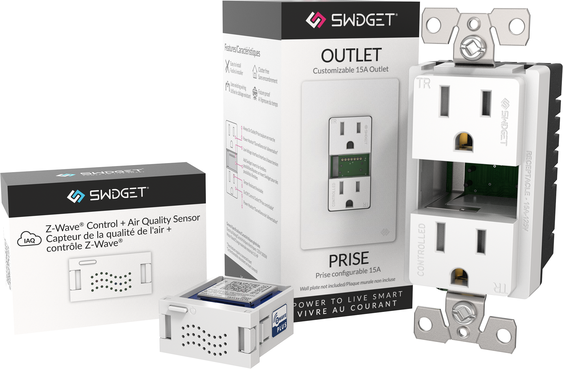
Short Description | The Swidget Z-Wave™ Control + Air Quality Insert allows users to control and monitor a Swidget Device, and monitors Volatile Organic Compounds (VOCs), equivalent CO2, air pressure, temperature, and humidity to provide an Air Quality Index (AQI). The Swidget 15A Outlet offers unique smart features such as advanced automation, energy management capabilities, and external device and appliance regulation capabilities. |
|---|
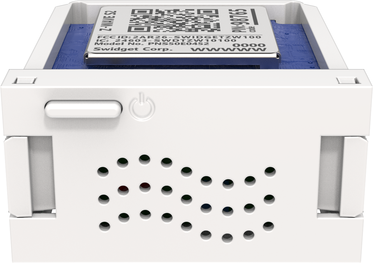
Long Description | The Swidget Z-Wave™ Control + Air Quality Insert is a modular smart home solution engineered for seamless integration with all Swidget Wiring Devices. Swidget's Z-Wave™ Devices and Inserts simplify the process of upgrading your home to a smart living space. Swidget Devices are installed in your home just like any other wiring devices, ensuring there is no unnecessary complexity during installation. Once your device is installed, simply select your desired sensor capability, and snap your Swidget Z-Wave™ Insert into the Swidget Wiring Device. The modularity of Swidget's Inserts ensures that the solution is adaptable to your needs as they change and future-proofs your investment by enabling you to adapt to new technologies, sensors, and trends as they emerge.
The Swidget Z-Wave™ Control + Air Quality Insert allows the user to control and monitor a Swidget Device. The Swidget Air Quality Insert monitors Volatile Organic Compounds (VOCs), equivalent CO2, air pressure, temperature, and humidity to provide an Air Quality Index (AQI). Passively monitor your room's air quality, humidity, and temperature through Swidget's App or actively use them in automations to optimize and improve your living space. The Swidget Air Quality Insert works directly out of the box when paired with Swidget's 20/40/60 Timer Control Switch and Panasonic ventilation products such as WhisperQuiet bathroom fans and Panasonic Energy Recovery Ventilator (ERV) systems.
When a Z-Wave™ Control + Air Quality Insert is installed in a 15A Outlet, the combination offers unique smart features, including advanced automation and energy management capabilities. Control and monitor the energy consumption of your Wiring Device, identifying areas of potential improvement and removing unnecessary vampire loads across the house. This promotes efficient energy usage, which ultimately leads to cost savings and a reduced carbon footprint. Furthermore, the 15A Outlet allows for external device and appliance regulation capabilities. Take control of any device powered through the lower receptacle through your Z-Wave™ controller for added functionality and device integration. |
|---|
Brand | Swidget |
|---|
Product Identifier | ZW008UWA/01 |
|---|
Product Line | Swidget Z-Wave Inserts |
|---|
OEM Version | HW: 01 FW: 01.00 |
|---|
Hardware Platform | ZGM230SA |
|---|
Z-Wave Version | 7.18.3 |
|---|
Library Type | END_NODE_ENHANCED_232 |
|---|
Device Type | Binary Switch DT |
|---|
Role Type | ROLE_TYPE_END_NODE_ALWAYS_ON |
|---|
Manufacturer ID | 0x0345 |
|---|
Product Type ID | 0x0105 |
|---|
Product ID | 0x0002 |
|---|
User Icon | 0x0700 |
|---|
Installer Icon | 0x0700 |
|---|
Frequency Plans | US: 916.00MHz, 908.40MHz |
|---|
Categories | Sensors, Energy Meters, On/Off Switches/Devices |
|---|
Countries / Regions | Canada, United States of America |
|---|
Supported Command Classes | Identifier | Name | Key | Version |
|---|
COMMAND_CLASS_BASIC_V2 | Basic V2 | 0x20 | 2 | COMMAND_CLASS_SWITCH_BINARY_V2 | Binary Switch V2 | 0x25 | 2 | COMMAND_CLASS_CONFIGURATION_V4 | Configuration V4 | 0x70 | 4 | COMMAND_CLASS_METER_V5 | Meter V5 | 0x32 | 5 | COMMAND_CLASS_SENSOR_MULTILEVEL_V11 | Multilevel Sensor V11 | 0x31 | 11 | COMMAND_CLASS_NOTIFICATION_V8 | Notification V8 | 0x71 | 8 | COMMAND_CLASS_ASSOCIATION_V2 | Association V2 | 0x85 | 2 | COMMAND_CLASS_ASSOCIATION_GRP_INFO_V3 | Association Group Information (AGI) V3 | 0x59 | 3 | COMMAND_CLASS_DEVICE_RESET_LOCALLY | Device Reset Locally | 0x5A | 1 | COMMAND_CLASS_FIRMWARE_UPDATE_MD_V5 | Firmware Update Meta Data V5 | 0x7A | 5 | COMMAND_CLASS_INDICATOR_V3 | Indicator V3 | 0x87 | 3 | COMMAND_CLASS_MANUFACTURER_SPECIFIC_V2 | Manufacturer Specific V2 | 0x72 | 2 | COMMAND_CLASS_MULTI_CHANNEL_ASSOCIATION_V3 | Multi Channel Association V3 | 0x8E | 3 | COMMAND_CLASS_VERSION_V3 | Version V3 | 0x86 | 3 | COMMAND_CLASS_ZWAVEPLUS_INFO_V2 | Z-Wave Plus Info V2 | 0x5E | 2 | COMMAND_CLASS_MULTI_CHANNEL_V4 | Multi Channel V4 | 0x60 | 4 | COMMAND_CLASS_SECURITY | Security 0 | 0x98 | 1 | COMMAND_CLASS_SECURITY_2 | Security 2 | 0x9F | 1 | COMMAND_CLASS_SUPERVISION | Supervision | 0x6C | 1 | COMMAND_CLASS_TRANSPORT_SERVICE_V2 | Transport Service V2 | 0x55 | 2 | COMMAND_CLASS_POWERLEVEL | Powerlevel | 0x73 | 1 |
|
|---|
S2 Classes | S2_AUTHENTICATED, S2_UNAUTHENTICATED |
|---|
Documents | Category | File |
|---|
Adv_Manual | | Manual_English | |
|
|---|
Features | Feature | Values |
|---|
Color | | Electric Load Type | Value |
|---|
Inductive (e.g. Motor) |
| Firmware Updatable | Value |
|---|
Updatable by Consumer via Internet |
| Neutral Wire Required | | Switch Load Capacity Current | | Switch Load Capacity Volt-Ampere | | Switch Load Capacity Watts | | Switch Type | Value |
|---|
Push Button with Indicator |
|
|
|---|
Association Groups | Group Number | Maximum Nodes Supported | End Point ID | Group Name | Profile |
|---|
1 | 5 | 0 | Lifeline | 0x0001 | 2 | 5 | 0 | Switch | 0x2001 | 3 | 5 | 0 | High Power 1 | 0x3201 | 4 | 5 | 0 | Low Power 1 | 0x3201 | 5 | 5 | 0 | High Power 2 | 0x3201 | 6 | 5 | 0 | Low Power 2 | 0x3201 | 7 | 5 | 0 | Air Quality | 0x710D | 8 | 5 | 0 | High Temperature | 0x3101 | 9 | 5 | 0 | Low Temperature | 0x3101 | 10 | 5 | 0 | High Humidity | 0x3105 | 11 | 5 | 0 | Low Humidity | 0x3105 | 1 | 0 | 1 | Lifeline | 0x0001 | 1 | 0 | 2 | Lifeline | 0x0001 |
|
|---|
Configuration Parameters | Parameter Number | Name | Description | Format | Size | Min Value | Max Value | Default Value | Read-only | Flag Advanced |
|---|
1 | Power 1 High Entry Level | Refer to documentation | 1 | 2 | 0 | 0 | 0x0960 | | | 2 | Power 1 Low Entry Level | Refer to documentation | 1 | 2 | 0 | 0 | 0x0000 | | | 3 | Power 1 High Exit Level | Refer to documentation | 1 | 2 | 0 | 0 | 0x0960 | | | 4 | Power 1 Low Exit Level | Refer to documentation | 1 | 2 | 0 | 0 | 0x0000 | | | 5 | Power 1 High Delay | Refer to documentation | 1 | 2 | 0 | 0 | 0x0000 | | | 6 | Power 1 Low Delay | Refer to documentation | 1 | 2 | 0 | 0 | 0x0000 | | | 7 | Power 1 Periodic Report | Refer to documentation | 1 | 2 | 0 | 0 | 0x0E10 | | | 8 | Power 1 Change Report | Refer to documentation | 1 | 2 | 0 | 0 | 0x000A | | | 9 | Power 1 Renotification Delay | Refer to documentation | 1 | 2 | 0 | 0 | 0x0000 | | | 10 | Power 1 High Entry SET Value | Refer to documentation | 1 | 1 | 0 | 0 | 0xFF | | | 11 | Power 1 High Exit SET Value | Refer to documentation | 1 | 1 | 0 | 0 | 0x00 | | | 24 | Power 2 High Entry Level | Refer to documentation | 1 | 2 | 0 | 0 | 0x0960 | | | 25 | Power 2 Low Entry Level | Refer to documentation | 1 | 2 | 0 | 0 | 0x0000 | | | 31 | Power 2 Change Report | Refer to documentation | 1 | 2 | 0 | 0 | 0x000A | | | 64 | Air Quality Level 1 Index | Refer to documentation | 1 | 2 | 0 | 0 | 0x0064 | | | 65 | Air Quality Level 2 Index | Refer to documentation | 1 | 2 | 0 | 0 | 0x00AF | | | 66 | Air Quality Level 3 Index | Refer to documentation | 1 | 2 | 0 | 0 | 0x00FA | | | 67 | Air Quality Alert Level | Refer to documentation | 1 | 1 | 0 | 0 | 0x02 | | | 68 | Air Quality Alert Delay | Refer to documentation | 1 | 2 | 0 | 0 | 0x0000 | | | 69 | Air Quality Renotification Delay | Refer to documentation | 1 | 2 | 0 | 0 | 0x012C | | | 70 | Air Quality VOC Periodic Report | Refer to documentation | 1 | 2 | 0 | 0 | 0x0E10 | | | 72 | Air Quality Alert Entry SET Value | Refer to documentation | 1 | 1 | 0 | 0 | 0xFF | | | 73 | Air Quality Alert Exit SET Value | Refer to documentation | 1 | 1 | 0 | 0 | 0x00 | | | 74 | Air Quality Actions | Refer to documentation | 3 | 2 | 0 | 0 | 0x0013 | | | 80 | Temperature High Entry Level | Refer to documentation | 0 | 2 | 0 | 0 | 0x00E6 | | | 81 | Temperature Low Entry Level | Refer to documentation | 0 | 2 | 0 | 0 | 0x00AA | | | 82 | Temperature High Exit Level | Refer to documentation | 0 | 2 | 0 | 0 | 0x00E6 | | | 83 | Temperature Low Exit Level | Refer to documentation | 0 | 2 | 0 | 0 | 0x00AA | | | 84 | Temperature High Delay | Refer to documentation | 1 | 2 | 0 | 0 | 0x0000 | | | 85 | Temperature Low Delay | Refer to documentation | 1 | 2 | 0 | 0 | 0x0000 | | | 86 | Temperature Periodic Report | Refer to documentation | 1 | 2 | 0 | 0 | 0x0E10 | | | 87 | Temperature Change Report | Refer to documentation | 1 | 1 | 0 | 0 | 0x0A | | | 88 | Temperature Renotification Delay | Refer to documentation | 1 | 2 | 0 | 0 | 0x0000 | | | 89 | Temperature High Entry SET Value | Refer to documentation | 1 | 1 | 0 | 0 | 0xFF | | | 90 | Temperature High Exit SET Value | Refer to documentation | 1 | 1 | 0 | 0 | 0x00 | | | 91 | Temperature Low Entry SET Value | Refer to documentation | 1 | 1 | 0 | 0 | 0xFF | | | 92 | Temperature Low Exit SET Value | Refer to documentation | 1 | 1 | 0 | 0 | 0x00 | | | 93 | Temperature High Actions | Refer to documentation | 3 | 2 | 0 | 0 | 0x00E3 | | | 94 | Temperature Low Actions | Refer to documentation | 3 | 2 | 0 | 0 | 0x00E3 | | | 95 | Temperature Units | Refer to documentation | 2 | 1 | 0 | 0 | 0x00 | | | 128 | Humidity High Entry Level | Refer to documentation | 1 | 1 | 0 | 0 | 0x64 | | | 129 | Humidity Low Entry Level | Refer to documentation | 1 | 1 | 0 | 0 | 0x00 | | | 130 | Humidity High Exit Level | Refer to documentation | 1 | 1 | 0 | 0 | 0x64 | | | 131 | Humidity Low Exit Level | Refer to documentation | 1 | 1 | 0 | 0 | 0x00 | | | 132 | Humidity High Delay | Refer to documentation | 1 | 2 | 0 | 0 | 0x0000 | | | 133 | Humidity Low Delay | Refer to documentation | 1 | 2 | 0 | 0 | 0x0000 | | | 134 | Humidity Periodic Report | Refer to documentation | 1 | 2 | 0 | 0 | 0x0E10 | | | 135 | Humidity Change Report | Refer to documentation | 1 | 1 | 0 | 0 | 0x0A | | | 136 | Humidity Renotification Delay | Refer to documentation | 1 | 2 | 0 | 0 | 0x0000 | | | 137 | Humidity High Entry SET Value | Refer to documentation | 1 | 1 | 0 | 0 | 0xFF | | | 138 | Humidity High Exit SET Value | Refer to documentation | 1 | 1 | 0 | 0 | 0x00 | | | 140 | Humidity Low Exit SET Value | Refer to documentation | 1 | 1 | 0 | 0 | 0x00 | | | 142 | Humidity High Actions | Refer to documentation | 3 | 2 | 0 | 0 | 0x0003 | | | 143 | Humidity Low Actions | Refer to documentation | 3 | 2 | 0 | 0 | 0x0003 | | | 152 | System Status | Refer to documentation | 1 | 4 | 0 | 0 | 0x00000000 | Yes | Yes | 139 | Humidity Low Entry SET Value | Refer to documentation | 1 | 1 | 0 | 0 | 0xFF | | | 153 | System LED Brightness | Refer to documentation | 1 | 1 | 0 | 0 | 0x64 | | | 154 | System Options | Refer to documentation | 3 | 2 | 0 | 0 | 0x0000 | | |
|
|---|
Texts | ID | Description | Value |
|---|
8 | Where to find S2 DSK on product | Use the Z-Wave controller / hub app or interface to scan the QR code located on the security card or directly on the insert, or manually enter the 5 digit PIN or insert's full DSK (Device Specific Key) as required. | 1 | Classic Inclusion | Follow network ADD steps for your Z-Wave controller / hub.
Lightly press Insert push button and hold for 5-10 seconds until the LED illuminates solid blue, then release. LED will flash blue to indicate ADD mode is enabled. No manual or external Z-Wave operations are possible during this activity.
Insert will remain in ADD mode for up to 30 seconds. If successful, LED will be solid blue for 5 seconds then return to the normal operational state. IF FAILED to connect after 30 seconds, the red LED will flash for 3 seconds, indicating no or failed network ADD. If necessary, consult your Z-Wave controller/hub manual and retry. | 2 | Classic Exclusion | Follow network REMOVE steps for your Z-Wave controller / hub.
Lightly press Insert push button and hold for 5-10 seconds then release. LED will flash blue to indicate REMOVE mode is enabled. No manual or external Z-Wave operations are possible during this activity.
Insert will remain in REMOVE mode for up to 30 seconds. If successful, LED will be solid blue for 5 seconds then return to the normal operational state. If FAILED to connect after 60 seconds, red LED will flash indicating no or failed network REMOVE. If necessary, consult your Z-Wave controller / hub manual and retry. | 5 | Factory Reset Procedure | Should only be used when the original controller is inoperable or has been replaced.
Lightly press Insert push button and hold for 10-15 seconds until the LED turns SOLID RED, and then release. |
|
|---|
Supported / Controlled Meter Types | Meter Type | Rate Type |
|---|
Electric meter | Import (consumed) |
|
|---|
Supported Notification Types | Notification Type | Event / State |
|---|
Heat Alarm | Heat sensor status: Overheat detected | Heat Alarm | Heat sensor status: Under heat detected | Home Health | VOC level status: Volatile Organic Compound level |
|
|---|
Supported Multilevel Sensors | Multilevel Sensor Type |
|---|
Air temperature | Humidity | Volatile Organic Compound level |
|
|---|
Supports NWI | Yes |
|---|
Supports Explorer Frames | Yes |
|---|
Supports SmartStart | Yes |
|---|
Radio Range Z-Wave (m) | 40 |
|---|