| Product Recognition | |
|---|
| Certification Number | ZC14-26020583 |
|---|
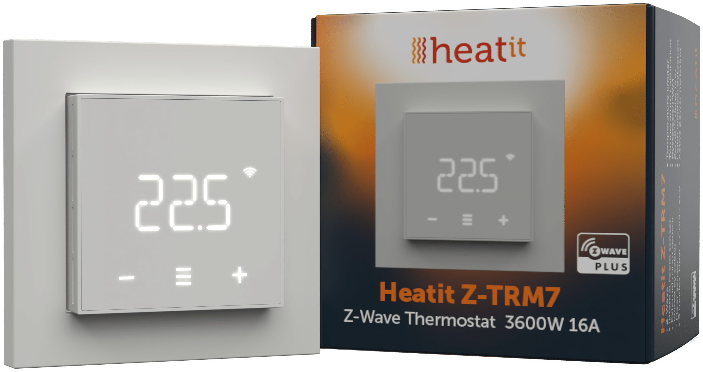
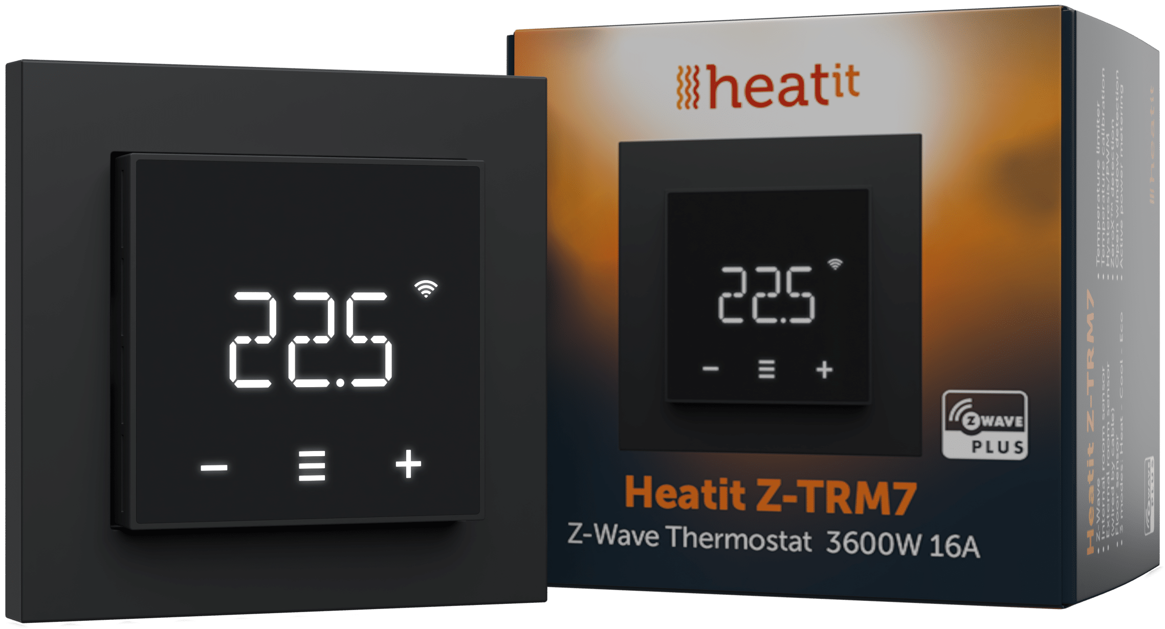
| Name | Heatit Z-TRM7 |
|---|
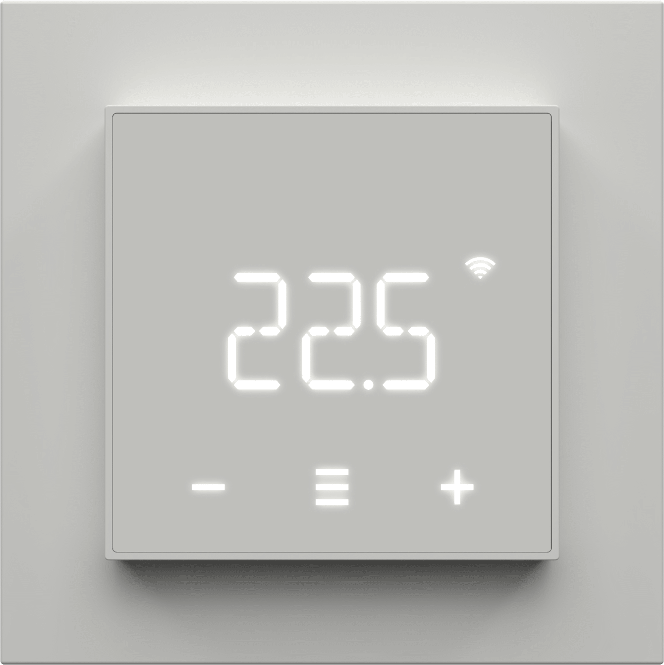
| Short Description | Heatit Z-TRM7 is an electronic thermostat designed for electrical heating and water based heating control.
Heatit Z-TRM7 has 3 modes; Heat - Cool and Eco.
Heatit Z-TRM7 has active power metering, and it gives you the real time information about the power consumption. |
|---|
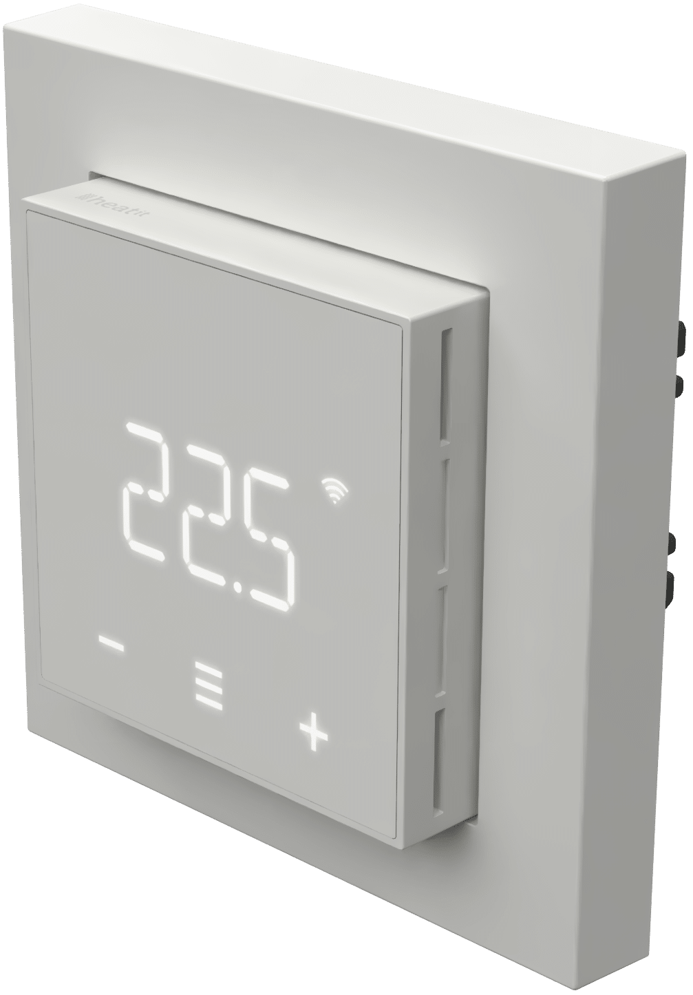
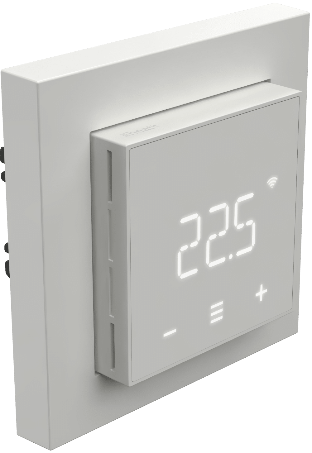
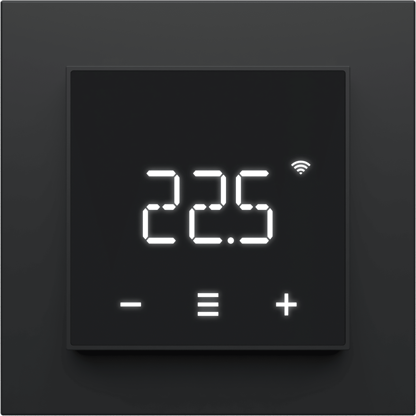
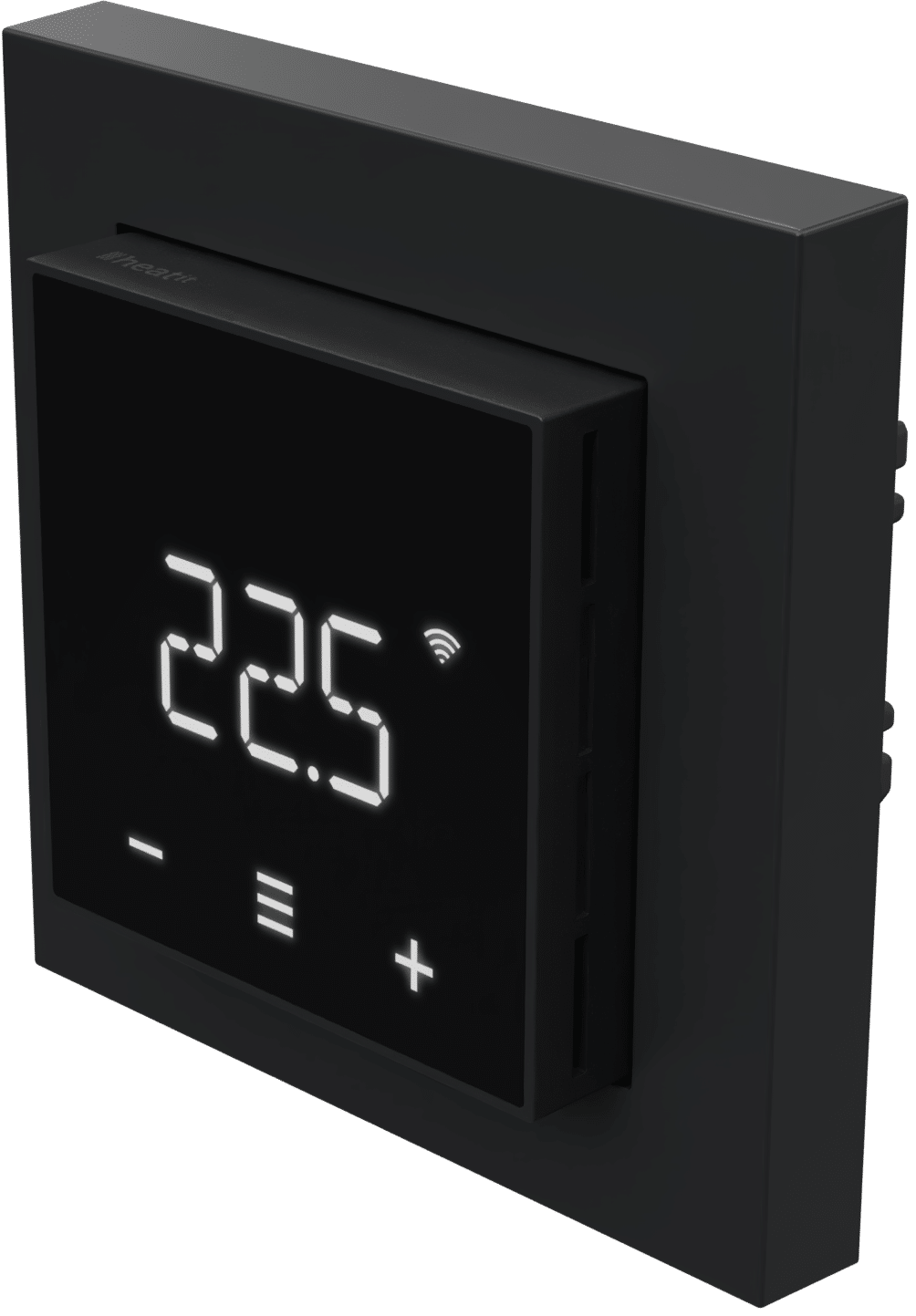
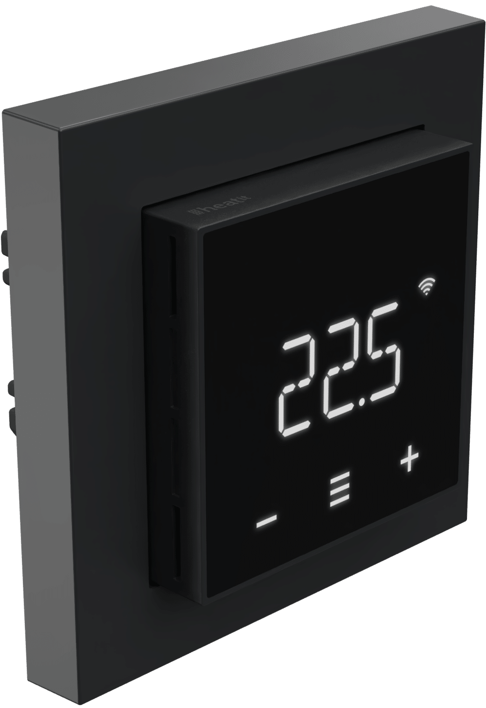
| Description | Heatit Z-TRM7 is an electronic thermostat designed for electrical heating and water based heating control. The thermostat can be controlled through your Z-Wave® network, or via the buttons on the front of the thermostat. The thermostat features a user-friendly interface, complies with the Eco-Design directive and has an easy-to-read LED display.
Heatit Z-TRM7 has 3 modes; Heat - Cool and Eco.
The thermostat fits in standard European junction boxes and may be used with most System 55 frames. It has a sturdy metal frame for secure fastening in the junction box. The thermostat has one built-in room temperature sensor. Two additional external temperature sensors may also be connected.
Heatit Z-TRM7 has active power metering, and it gives you the real time information about the power consumption. It also allows you to set the power metering value manually in case of connection with a contactor.
The device is equipped with ZeroX™ technology, which ensures the relay switches at 0V when turning on and off. This technology significantly extends the thermostat’s lifespan.
The thermostat can be set up with multiple associations and can be used as a master thermostat. It can control up to 10 thermostats and 10 external relays e.g wall plugs. |
|---|
| Brand | Heatit |
|---|
| Brand Owner | Heatit Controls AB |
|---|
| Identifier | Z-TRM7 |
|---|
| Product Line | Thermostat |
|---|
| OEM Version | HW: 01 FW: 02.00:01.02 |
|---|
| Hardware Platform | EFR32ZG23A |
|---|
| Z-Wave Version | 7.18.8 |
|---|
| Library Type | END_NODE_ENHANCED_232 |
|---|
| Device Type | Thermostat DT |
|---|
| Role Type | ROLE_TYPE_END_NODE_ALWAYS_ON |
|---|
| Manufacturer ID | 0x019B |
|---|
| Product Type ID | 0x0030 |
|---|
| Product ID | 0x3006 |
|---|
| User Icon | 0x1201 |
|---|
| Installer Icon | 0x1200 |
|---|
| Frequency Plans | EU: 869.85MHz, 868.40MHz |
|---|
| Categories | Thermostats |
|---|
| Countries / Regions | European Union |
|---|
| Supported Command Classes | | Identifier | Name | Key | Version |
|---|
| COMMAND_CLASS_BASIC_V2 | Basic V2 | 0x20 | 2 | | COMMAND_CLASS_CONFIGURATION_V4 | Configuration V4 | 0x70 | 4 | | COMMAND_CLASS_METER_V5 | Meter V5 | 0x32 | 5 | | COMMAND_CLASS_SENSOR_MULTILEVEL_V11 | Multilevel Sensor V11 | 0x31 | 11 | | COMMAND_CLASS_NOTIFICATION_V8 | Notification V8 | 0x71 | 8 | | COMMAND_CLASS_PROTECTION | Protection | 0x75 | 1 | | COMMAND_CLASS_THERMOSTAT_MODE_V3 | Thermostat Mode V3 | 0x40 | 3 | | COMMAND_CLASS_THERMOSTAT_OPERATING_STATE | Thermostat Operating State | 0x42 | 1 | | COMMAND_CLASS_THERMOSTAT_SETPOINT_V3 | Thermostat Setpoint V3 | 0x43 | 3 | | COMMAND_CLASS_ASSOCIATION_V2 | Association V2 | 0x85 | 2 | | COMMAND_CLASS_ASSOCIATION_GRP_INFO_V3 | Association Group Information (AGI) V3 | 0x59 | 3 | | COMMAND_CLASS_DEVICE_RESET_LOCALLY | Device Reset Locally | 0x5A | 1 | | COMMAND_CLASS_FIRMWARE_UPDATE_MD_V5 | Firmware Update Meta Data V5 | 0x7A | 5 | | COMMAND_CLASS_INDICATOR_V3 | Indicator V3 | 0x87 | 3 | | COMMAND_CLASS_MANUFACTURER_SPECIFIC_V2 | Manufacturer Specific V2 | 0x72 | 2 | | COMMAND_CLASS_MULTI_CHANNEL_ASSOCIATION_V3 | Multi Channel Association V3 | 0x8E | 3 | | COMMAND_CLASS_VERSION_V3 | Version V3 | 0x86 | 3 | | COMMAND_CLASS_ZWAVEPLUS_INFO_V2 | Z-Wave Plus Info V2 | 0x5E | 2 | | COMMAND_CLASS_MULTI_CHANNEL_V4 | Multi Channel V4 | 0x60 | 4 | | COMMAND_CLASS_SECURITY | Security 0 | 0x98 | 1 | | COMMAND_CLASS_SECURITY_2 | Security 2 | 0x9F | 1 | | COMMAND_CLASS_SUPERVISION | Supervision | 0x6C | 1 | | COMMAND_CLASS_TRANSPORT_SERVICE_V2 | Transport Service V2 | 0x55 | 2 | | COMMAND_CLASS_POWERLEVEL | Powerlevel | 0x73 | 1 |
|
|---|
| S2 Classes | S2_AUTHENTICATED, S2_UNAUTHENTICATED |
|---|
| Documents | |
|---|
| Features | | Feature | Values |
|---|
| Color | | | Firmware Updatable | | Value |
|---|
| Updatable by Consumer by RF |
| | IP (Ingress Protection) Rated | | | Neutral Wire Required | | | Switch Load Capacity Watts | | | Thermostat Modes | | Value |
|---|
| Heat | | Cool | | Energy Save Heat |
| | Thermostat Power Source | | Value |
|---|
| Mains powered (120V/240V) |
|
|
|---|
| Association Groups | | Group Number | Maximum Nodes Supported | End Point ID | Group Name | Profile |
|---|
| 1 | 1 | 0 | Lifeline | 0x0001 | | 1 | 0 | 1 | Lifeline | 0x0001 | | 2 | 10 | 1 | Binary Switch Set | 0x2001 | | 3 | 10 | 1 | Thermostat Setpoint Set | 0x2002 | | 4 | 10 | 1 | Thermostat Mode Set | 0x2003 | | 1 | 0 | 2 | Lifeline | 0x0001 | | 1 | 0 | 3 | Lifeline | 0x0001 | | 1 | 0 | 4 | Lifeline | 0x0001 | | 2 | 10 | 0 | Binary Switch Set | 0x2001 | | 3 | 10 | 0 | Thermostat Setpoint Set | 0x2002 | | 4 | 10 | 0 | Thermostat Mode Set | 0x2003 |
|
|---|
| Configuration Parameters | | Parameter Number | Name | Description | Format | Size | Min Value | Max Value | Default Value |
|---|
| 1 | Disable buttons | Disable or enable local control | 2 | 1 | 0 | 0 | 0x00 | | 2 | Sensor mode(OPER) | Select sensor mode of the device. | 2 | 1 | 0 | 0 | 0x01 | | 3 | Sensor value(SEN) | Select resistance of the connected NTC | 2 | 1 | 0 | 0 | 0x00 | | 4 | Internal sensor min temp limit | Set minimum setpoint for Internal sensor | 1 | 2 | 0 | 0 | 0x0032 | | 5 | Floor sensor min temp limit | Set minimum setpoint for Floor sensor | 1 | 2 | 0 | 0 | 0x0032 | | 6 | External sensor min temp limit | Set minimum setpoint for External sensor | 1 | 2 | 0 | 0 | 0x0032 | | 7 | Internal sensor max temp limit | Set maximum setpoint for Internal sensor | 1 | 2 | 0 | 0 | 0x0190 | | 8 | Floor sensor max temp limit | Set maximum setpoint for Floor sensor | 1 | 2 | 0 | 0 | 0x0190 | | 9 | External sensor max temp limit | Set maximum setpoint for External sensor | 1 | 2 | 0 | 0 | 0x0190 | | 10 | Internal sensor calibration (CAR) | Manually calibrate the Internal sensor | 0 | 1 | 0 | 0 | 0x00 | | 11 | Floor sensor calibration (CAF) | Manually calibrate the Floor sensor | 0 | 1 | 0 | 0 | 0x00 | | 17 | Standby display brightness (BR2) | Set brightness during standby state | 1 | 1 | 0 | 0 | 0x05 | | 23 | Cooling setpoint | Set the setpoint for Cooling mode | 1 | 2 | 0 | 0 | 0x00B4 | | 24 | ECO setpoint | Set the setpoint for ECO mode | 1 | 2 | 0 | 0 | 0x00B4 | | 25 | Power regulator active time | Active time of power regulator mode | 1 | 1 | 0 | 0 | 0x02 |
|
|---|
| Texts | | ID | Description | Value |
|---|
| 8 | Where to find S2 DSK on product | The QR-Code is needed when including a device using S2 security or SmartStart. The DSK can be found in the QR-Code and is located;
• On the product.
• In the Quick Guide.
• On the packaging box/gift box. | | 5 | Factory Reset Procedure | Enter the menu by holding the Center button for about 5 seconds, navigate in the menu with the ”+” button til you see FACT. Press the Center button until you see “-- --” blinking in the display, then hold for about 5 seconds to perform a reset.
You may also initiate a reset by holding the Right and Center buttons for 60 seconds.
When either of these procedures has been performed, the thermostat will perform a complete factory reset. The device will display “RES” for 5 seconds while performing a factory reset. When “RES” is no longer displayed, the thermostat has been reset.
Please use this procedure only when the network primary controller is missing or otherwise inoperable. | | 1 | Classic Inclusion | Add
The primary controller/gateway has a mode for adding devices. Please refer to your primary controller manual on how to set the primary controller in add mode. The device may only be added to the network if the primary controller is in add mode.
An always listening node must be powered continuously and reside in a fixed position in the installation to secure the routing table. Adding the device within a 2 meter range from the gateway can minimize faults during the Interview process.
Standard (Manual)
Add mode is indicated on the device by rotating LED segments on the display. It indicates this for 90 seconds until a timeout occurs, or until the device has been added to the network. Configuration mode can also be cancelled by performing the same procedure used for starting
Configuration mode.
1. Hold the Center button for 5 seconds.
The display will show “OFF”.
2. Press the ”+” button once to see “CON” in the display.
3. Start the add device process in your primary controller.
4. Start the configuration mode on the thermostat by holding the Center button for approximately 2 seconds.
The device is now ready for use with default settings.
If inclusion fails, please perform a ”remove device” process and try again. If inclusion fails again, please see “Factory reset”. | | 2 | Classic Exclusion | Remove
The primary controller/gateway has a mode for removing devices. Please refer to your primary controller manual on how to set the primary controller in remove mode. The device may only be removed from the network if the primary controller is in remove mode.
When the device is removed from the network, it will NOT revert to factory settings.
Standard (Manual)
Remove mode is indicated on the device by rotating LED segments on the display. It indicates this for 90 seconds until a timeout occurs, or until the device has been removed from the network. Configuration mode can also be cancelled by performing the same procedure used for starting
Configuration mode.
1. Hold the Center button for 5 seconds.
The display will show “OFF”.
2. Press the ”+” button once to see “CON” in the display.
3. Start the remove device process in your primary controller.
4. Start the configuration mode on the thermostat by holding the Center button for approximately 2 seconds.
NB! When the device is removed from the gateway, the parameters are not reset. To reset the parameters, see Chapter ”Factory reset”. |
|
|---|
| Supported / Controlled Meter Types | | Meter Type | Rate Type |
|---|
| Electric meter | Import (consumed) |
|
|---|
| Supported Notification Types | | Notification Type | Event / State |
|---|
| Heat Alarm | Heat sensor status: Overheat detected | | Power Management | Over-load status: Over-load detected |
|
|---|
| Supported Multilevel Sensors | | Multilevel Sensor Type |
|---|
| Air temperature |
|
|---|
| Supports NWI | Yes |
|---|
| Supports Explorer Frames | Yes |
|---|
| Supports SmartStart | Yes |
|---|