| Product Recognition | |
|---|
| Certification Number | ZC10-18096234 |
|---|
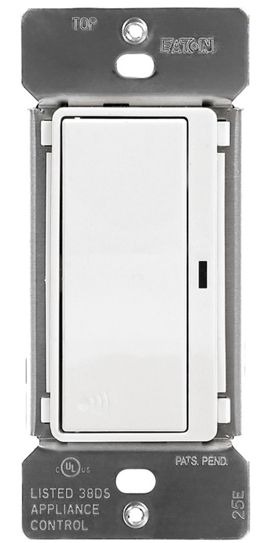
| Name | Eaton’s Z-Wave Plus Wireless Switch |
|---|
| Short Description | Eaton’s Z-Wave plus wireless switch replaces regular switches (where a neutral is present) to provide local and remote ON/OFF control for most common residential lighting loads including LEDs and certain motor loads. |
|---|
| Long Description | Eaton’s Z-Wave plus wireless switch replaces regular switches (where a neutral is present) to provide local and remote ON/OFF control for most common residential lighting loads including LEDs and certain motor loads. Each switch can be manually and remotely controlled by commands sent from your compatible Z-Wave certified controller.
Features & Benefits:
• Replaces standard switch to add local and wireless control
• Single pole and 3-Way control: Use with standard 3-Way switch or Z-Wave Plus Accessory RF9617
• Neutral is required for installation
• Supports motors loads up to ½ HP
• Features blue load indicating LED light that can be dimmed in ON or OFF state |
|---|
| Brand | Eaton |
|---|
| Product Identifier | RF9601 |
|---|
| OEM Version | HW: 255 FW: 2.00 |
|---|
| Hardware Platform | ZM5101 |
|---|
| Z-Wave Version | 6.71.03 |
|---|
| Library Type | SLAVE_ENHANCED_232_NOFLIRS_NOMR |
|---|
| Device Type | On/Off Power Switch |
|---|
| Role Type | ROLE_TYPE_SLAVE_ALWAYS_ON |
|---|
| Manufacturer ID | 0x001A |
|---|
| Product Type ID | 0x534C |
|---|
| Product ID | 0x0503 |
|---|
| User Icon | 0x0700 |
|---|
| Installer Icon | 0x0700 |
|---|
| Frequency Plans | US: 916.00MHz, 908.40MHz |
|---|
| Categories | All Lighting Devices, Lighting Accessories |
|---|
| Countries / Regions | United States of America |
|---|
| Supported Command Classes | | Identifier | Name | Key | Version |
|---|
| COMMAND_CLASS_SCENE_ACTUATOR_CONF | Scene Actuator Conf | 0x2C | 1 | | COMMAND_CLASS_NODE_NAMING | Node Naming | 0x77 | 1 | | COMMAND_CLASS_POWERLEVEL | Powerlevel | 0x73 | 1 | | COMMAND_CLASS_ALARM | Alarm | 0x71 | 1 | | COMMAND_CLASS_SWITCH_BINARY | Switch Binary | 0x25 | 1 | | COMMAND_CLASS_CONFIGURATION | Configuration | 0x70 | 1 | | COMMAND_CLASS_TRANSPORT_SERVICE_V2 | Transport Service V2 | 0x55 | 2 | | COMMAND_CLASS_VERSION_V2 | Version V2 | 0x86 | 2 | | COMMAND_CLASS_DEVICE_RESET_LOCALLY | Device Reset Locally | 0x5A | 1 | | COMMAND_CLASS_ZWAVEPLUS_INFO_V2 | Z-Wave Plus Info V2 | 0x5E | 2 | | COMMAND_CLASS_ASSOCIATION_V2 | Association V2 | 0x85 | 2 | | COMMAND_CLASS_ASSOCIATION_GRP_INFO | Association Group Info | 0x59 | 1 | | COMMAND_CLASS_BASIC_V2 | Basic V2 | 0x20 | 2 | | COMMAND_CLASS_SECURITY_2 | Security S2 | 0x9F | 1 | | COMMAND_CLASS_SUPERVISION | Supervision | 0x6C | 1 | | COMMAND_CLASS_PROTECTION | Protection | 0x75 | 1 | | COMMAND_CLASS_SCENE_ACTIVATION | Scene Activation | 0x2B | 1 | | COMMAND_CLASS_FIRMWARE_UPDATE_MD_V2 | Firmware Update Meta-Data V2 | 0x7A | 2 | | COMMAND_CLASS_MANUFACTURER_SPECIFIC_V2 | Manufacturer Specific V2 | 0x72 | 2 |
|
|---|
| Controlled Command Classes | | Identifier | Name | Key | Version |
|---|
| COMMAND_CLASS_BASIC_V2 | Basic V2 | 0x20 | 2 |
|
|---|
| S2 Classes | S2_UNAUTHENTICATED, S2_AUTHENTICATED |
|---|
| Documents | |
|---|
| Features | | Feature | Values |
|---|
| Firmware Updatable | | Value |
|---|
| Updatable by Consumer by RF |
| | Switch Load Capacity Current | | | Neutral Wire Required | | | Switch Type | | Value |
|---|
| Decorator Paddle Push with Indicator |
| | Z-Wave Scene Type | | | Electric Load Type | | Value |
|---|
| Incandescent | | Fluorescent | | MLV (Magnetic) | | ELV (Electronic) | | LED | | Dimmable LED | | Inductive (e.g. Motor) | | Dimmable Fluorescent | | Dimmable MLV (Magnetic) | | Dimmable ELV (Magnetic) |
|
|
|---|
| Association Groups | | Group Number | Maximum Nodes Supported | End Point ID | Description |
|---|
| 1 | 5 | 0 | Z-Wave Plus Lifeline | | 2 | 5 | 0 | ON/OFF |
|
|---|
| Configuration Parameters | | Parameter Number | Name | Description | Format | Size | Min Value | Max Value | Default Value | Parameter Values |
|---|
| 2 | Panic ON Time | The interval when the switch Turns ON when Panic Mode is set to ON | 0 | 1 | 0 | 127 | 1 | | From | To | Description |
|---|
| 0 | 127 | Panic ON Time |
| | 3 | Panic OFF Time | The interval when the switch Turns OFF when Panic Mode is set to ON | 0 | 1 | 0 | 127 | 1 | | From | To | Description |
|---|
| 0 | 127 | Panic OFF Time |
| | 5 | Power Up State | Power UP state allows the users to set the state the device will come ON after power is restored. 1 = OFF 2 = ON 3 = Last State Default is OFF | 0 | 1 | 1 | 3 | 1 | | From | To | Description |
|---|
| 1 | 1 | Turn OFF when Power is back | | 2 | 2 | Turn ON when Power is back | | 3 | 3 | Default to Last State when Power is Back |
| | 6 | Panic Mode Enable | Panic Mode allows Eaton Z-Wave devices to Turn ON/OFF at a press of button. 0 = OFF 1 = ON | 0 | 1 | 0 | 1 | 0 | | From | To | Description |
|---|
| 0 | 0 | Panic Mode is Turned OFF | | 1 | 1 | Panic Mode is Turned ON |
| | 1 | Delayed OFF Time | Turn the switch off with a preset delay. The default is 10 seconds. You can set this anywhere between 1 second till 127 seconds. The default is set at 10 | 0 | 1 | 0 | 127 | 10 | | From | To | Description |
|---|
| 0 | 127 | Delayed OFF Time |
|
|
|---|
| Texts | | ID | Description | Value |
|---|
| 1 | Inclusion | 1. To include this device in a Z-Wave network, select the command on your Z Wave controller for inclusion (Install, Add Device,
Add Node, Include Device, etc.). Then press the device ON/OFF button one time to include it in the network.
2. Based on the controller, the controller may ask you to scan the QR code or manually enter 5 digit code under the QR code
to install the device as a secured device. You may find this QR code on the device or included in device packaging.
3. After the Device is added to the network, the blue indicator LED will stop blinking. This indicates the device is installed in the Z-Wave
network. | | 2 | Exclusion | 1. To exclude this device from a Z-Wave network, select the setting on your Z-Wave controller for exclusion
(Uninstall, Remove Device, Remove Node, Exclude Device, etc.).
2. Once your controller is in exclusion mode, press the device ON/OFF button one time to exclude it from the network. The LED will start
blinking. | | 5 | Factory Reset | Please use this procedure only when the network primary controller is missing or otherwise inoperable.
The device could be reset locally. This will cause the device to be excluded from its network and restore to factory default.
Before leaving the network the switch will send a notification to the controller indicating its departure from the Z-Wave network.
1. Turn the device ON.
2. Press and hold ON/OFF button for 20 second till the LED flashes for the third time.
3. Release the ON/OFF button.
4. LED will start flashing rapidly. Once the LED starts blinking slowly, that indicates the device is not part of the network. |
|
|---|
| Supports NWI | Yes |
|---|
| Supports Explorer Frames | Yes |
|---|