| Product Recognition | |
|---|
| Certification Number | ZC14-22040102 |
|---|
| Name | Energy Driven Switch c 7 |
|---|
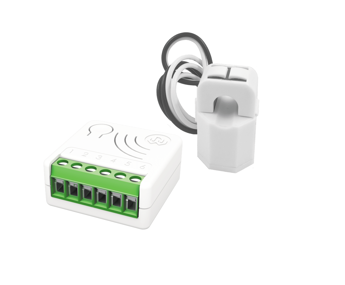
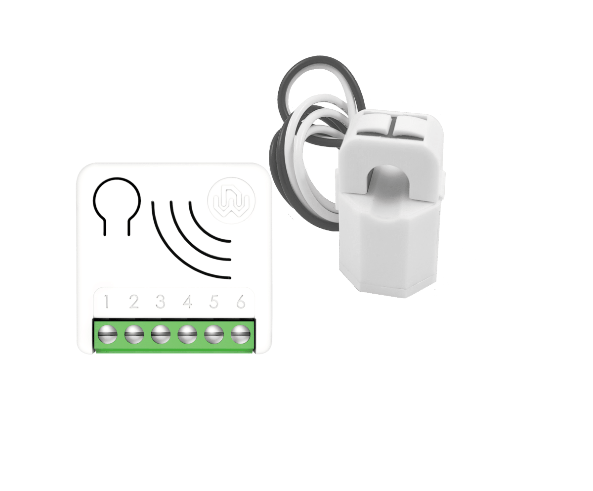
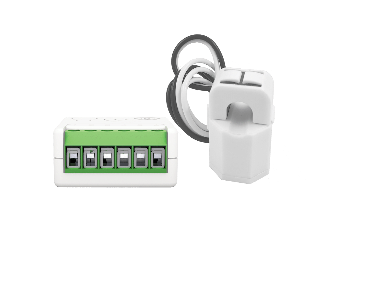
| Short Description | Energy Driven Switch C 7 monitors all parameters, usage, faults and overloads of the electrical system. A bi-directional meter that measures consumed and produced power. |
|---|
| Long Description | The device is a bi-directional meter capable of measuring both the consumed and produced power, equipped with a relay that can be activated to initiate specific scenarios in relation to detected power levels.
It is equipped with an external current transformer and can measure powers over 10 KW.
Electrical measurements: Energy produced and consumed, Instant power, Voltage RMS, Current RMS, Power Factor,
SPECIAL FEATURES
- Active Energy-saving management
Automatically connects and disconnects a specific load if the established threshold limit is exceeded, or supplies the required power, momentarily excluding non-priority loads.
- Management and prevention of electrical faults
Identifies malfunctions based on irregular consumption and to the maximum time of activity.
- Electrical overload management
Notifies or disconnects non-priority loads in the eventuality of system overloads.
- Timer Management
The device has a timer that can be configured to turn ON and/or OFF the local relay.
- Offline setup Mode
A unique feature that allows to configure some parameters without using any user interface.
- Zero Crossing
Equipped with contact protection technology (Zero Crossing) which reduces the electrical stress on the relay contacts and ensures a longer life. The open / closed switching of the device always occurs when the instantaneous value of voltage is 0.
Energy Driven Switch C 7 boasts the lowest energy consumption on the market.
This device is a security enabled Z-Wave Plus™ product.
Power Supply: 110 - 230 VAC±10% 50/60 Hz
Maximum Load on Relay: 3750 VA – 250VAC – 15 A
Extremely small size: 37x37x17 mm
New Z-Wave™ serie 700, SmartStart and S2 security |
|---|
| Brand | WiDom |
|---|
| Product Identifier | EDSC700 |
|---|
| Product Line | Z-Wave Product |
|---|
| OEM Version | HW: 01 FW: 07.00 |
|---|
| Hardware Platform | ZGM130S037HGN2 / ZGM130S037HGN1 |
|---|
| Z-Wave Version | 7.16.3 |
|---|
| Library Type | END_NODE_ENHANCED_232 |
|---|
| Device Type | Meter Sensor DT |
|---|
| Role Type | ROLE_TYPE_SLAVE_ALWAYS_ON |
|---|
| Manufacturer ID | 0x0149 |
|---|
| Product Type ID | 0x0004 |
|---|
| Product ID | 0x0009 |
|---|
| User Icon | 0x1000 |
|---|
| Installer Icon | 0x1000 |
|---|
| Frequency Plans | EU: 869.85MHz, 868.40MHz |
|---|
| Categories | Energy Meters |
|---|
| Countries / Regions | Algeria, Bahrain, Cyprus, Moldova |
|---|
| Supported Command Classes | | Identifier | Name | Key | Version |
|---|
| COMMAND_CLASS_ASSOCIATION_V2 | Association V2 | 0x85 | 2 | | COMMAND_CLASS_ASSOCIATION_GRP_INFO_V3 | Association Group Information (AGI) V3 | 0x59 | 3 | | COMMAND_CLASS_DEVICE_RESET_LOCALLY | Device Reset Locally | 0x5A | 1 | | COMMAND_CLASS_FIRMWARE_UPDATE_MD_V5 | Firmware Update Meta Data V5 | 0x7A | 5 | | COMMAND_CLASS_INDICATOR_V3 | Indicator V3 | 0x87 | 3 | | COMMAND_CLASS_MANUFACTURER_SPECIFIC_V2 | Manufacturer Specific V2 | 0x72 | 2 | | COMMAND_CLASS_MULTI_CHANNEL_ASSOCIATION_V3 | Multi Channel Association V3 | 0x8E | 3 | | COMMAND_CLASS_VERSION_V3 | Version V3 | 0x86 | 3 | | COMMAND_CLASS_ZWAVEPLUS_INFO_V2 | Z-Wave Plus Info V2 | 0x5E | 2 | | COMMAND_CLASS_SECURITY_2 | Security 2 | 0x9F | 1 | | COMMAND_CLASS_SUPERVISION | Supervision | 0x6C | 1 | | COMMAND_CLASS_TRANSPORT_SERVICE_V2 | Transport Service V2 | 0x55 | 2 | | COMMAND_CLASS_POWERLEVEL | Powerlevel | 0x73 | 1 | | COMMAND_CLASS_METER_V5 | Meter V5 | 0x32 | 5 | | COMMAND_CLASS_CONFIGURATION_V4 | Configuration V4 | 0x70 | 4 | | COMMAND_CLASS_APPLICATION_STATUS | Application Status | 0x22 | 1 | | COMMAND_CLASS_NOTIFICATION_V8 | Notification V8 | 0x71 | 8 |
|
|---|
| S2 Classes | S2_AUTHENTICATED, S2_UNAUTHENTICATED |
|---|
| Documents | | Category | Description | File |
|---|
| Manual_English | This version of the manual is the most updated, and integrates the changes based on the notes received. | MANUAL_EDSC_7_EN_WiDom150422.pdf |
|
|---|
| Association Groups | | Group Number | Maximum Nodes Supported | End Point ID | Group Name | Profile |
|---|
| 1 | 5 | 0 | Lifeline | 0x0001 | | 2 | 5 | 0 | Up Power Detected G1 | 0x2001 | | 3 | 5 | 0 | Up Power Detected G2 | 0x2002 | | 4 | 5 | 0 | Down Power Detected G1 | 0x2003 | | 5 | 5 | 0 | Down Power Detected G2 | 0x2004 |
|
|---|
| Configuration Parameters | | Parameter Number | Name | Description | Format | Size | Min Value | Max Value | Default Value |
|---|
| 23 | STARTUP_OUT | Define the output level on startup (0: OFF, 1: ON, 2: Previous status) | 2 | 1 | 0 | 0 | 0x00 | | 31 | OFF_TIMEOUT | Time in tenth of second after which the output will be switched Off. 0: OFF timer disabled | 1 | 4 | 0 | 0 | 0x00000000 | | 41 | DOWN_POWER_LOCAL_CONTROL | The value used to control the integrated Relay in case of Down Power Event.(0: OFF, 1: ON) | 2 | 1 | 0 | 0 | 0x01 | | 42 | METER_TYPE | Define how power value is treated (0: as is, 1: negative value 0, 2: positive value 0, 3: All positive, 4: All negative) | 2 | 1 | 0 | 0 | 0x03 | | 43 | CT_TYPE | Define the Model of Current Transformer connected to the device (1: Standard Type, 2: Type2 version) | 2 | 1 | 0 | 0 | 0x01 | | 44 | UP_POWER_REMOTE_CONTROL | The value used to control uP Power Group. (0-99: specific value, 100: ON) | 1 | 1 | 0 | 0 | 0x00 | | 45 | DOWN_POWER_REMOTE_CONTROL | The value used to control Down Power Group. (0-99: specific value, 100: ON) | 1 | 1 | 0 | 0 | 0x64 | | 46 | OVER_VOLTAGE_LIMIT | Define the Over Voltage Limit in tenth of volt | 1 | 2 | 0 | 0 | 0x09E2 | | 47 | DOWN_VOLTAGE_LIMIT | Define the Down Voltage Limit in tenth of volt | 1 | 2 | 0 | 0 | 0x0816 | | 50 | UP_POWER_LEVEL | Sets the level in Watts beyond which time of permanence above this level is calculated. 0: Up Power Event Disabled | 1 | 4 | 0 | 0 | 0x00000000 | | 51 | UP_POWER_TYPE | Define if the Up Power is consumed or produced (0: consumed, 1: produced) | 2 | 1 | 0 | 0 | 0x00 | | 52 | UP_POWER_FIRST_TIMEOUT | Define the time of permanence in seconds above the Up power level after which the First Up Power event occurs | 1 | 2 | 0 | 0 | 0x001e | | 53 | UP_POWER_NEXT_TIMEOUT | Define the time of permanence in seconds above the Up power level after which the Next Up Power event occurs | 1 | 2 | 0 | 0 | 0x0005 | | 54 | DOWN_POWER_LEVEL | Sets the level in Watt beyond which time of permanence below this level is calculated. 0: Down Power Event Disabled | 1 | 4 | 0 | 0 | 0x00000000 | | 55 | DOWN_POWER_TYPE | Define if the Down Power is consumed or produced (0: consumed, 1: produced) | 2 | 1 | 0 | 0 | 0x00 | | 56 | DOWN_POWER_FIRST_TIMEOUT | Define the time of permanence in seconds below the Down Power level after which the first Down Power event occurs | 1 | 2 | 0 | 0 | 0x001E | | 57 | DOWN_POWER_NEXT_TIMEOUT | Define the time of permanence in seconds below the Down Power level after which the next Up Down event occurs | 1 | 2 | 0 | 0 | 0x0005 | | 58 | PROTECTION_TIME | Define the minimum time is second after which an Up/Down Power Event can be trigger again | 1 | 2 | 0 | 0 | 0x003c | | 71 | METER_REPORT_MAX_DELAY | The Maximum Time in minute after which the next Meter sequence report will be sent | 1 | 1 | 0 | 0 | 0x0A | | 75 | METER_ISTANT_REPORT | The percentage change of Power from the last sent report that triggers a new meter report sequence | 1 | 1 | 0 | 0 | 0x14 | | 76 | REPORT_CONFIG | Define which Report scale will be sent. (0:none, 1:Energy , 4:Power, 16:Voltage, 32:Current, 64:Power Factor) | 3 | 1 | 0 | 0 | 0x75 |
|
|---|
| Texts | | ID | Description | Value |
|---|
| 8 | Where to find S2 DSK on product | Page 5 - S2 Secure inclusion- When adding Smart Serie 7 devices to a Z-Wave network with a controller supporting Security 2 Authenticated (S2), the PIN code of the Z-Wave Device Specific Key (DSK) is required. | | 1 | Classic Inclusion | All Smart Serie 7 devices are compatible with all Z-Wave/Z-Wave Plus certified controllers. The devices support both the Network Wide Inclusion mechanism (which offers the ability to be included in a network, even if the device is not directly connected to the controller) and Normal Inclusion.
By default, the inclusion procedure starts in Normal Inclusion mode and after a short timeout the procedure continues in Network Wide Inclusion mode that lasts for about 20 Seconds.
Only a controller can add the device into the network. After activating the inclusion function by the controller, the device can be added by setting it in Learn Mode.
Before including the device, the LED status indicator is solid RED. The adding of a device is executed by activating the adding procedure in the inclusion section of the controller interface and executing 1 or 3 click on the integrated button (the device is set in Learn Mode). As soon as the inclusion procedure initiates the LED indicator starts a sequence of GREEN-BLUE blinks. The device is included in the network when the LED status is OFF and the interview is completed. | | 2 | Classic Exclusion | Only a controller can remove the device from the network. After activating the exclusion function by the controller, the device can be removed by setting it in Learn Mode.
1 2 3 4 5 6
Energy Driven Switch C 7 Operating Instructions – www.widom.it 5
The procedure of exclusion can be activated by Removing a node from the Z-Wave network and executing 1 or 3 click on the integrated button; as soon as the exclusion initiates, the LED indicator starts a sequence of RED-BLUE blinks. The device is excluded from the network when the LED status indicator is solid RED and the App_status in the interface is OK. | | 5 | Factory Reset Procedure | The device can be reset to the original factory settings with 6 consecutive clicks on the integrated button.
After the reset is completed, the device will reboot and a RED solid led is showed.
INFO: If the reset is performed while the device is still part of a network, it notifies the other devices that it has been removed (Device Reset Locally Notification). | | 6 | Other Special Features | OTHER SPECIAL FEATURES
Timer Management
The device has a timer that can be configured to turn ON and/or OFF the local relay. The timer starts its counter after a relay commutation.
Active Energy management
Energy Driven Switch C 7 can implement an active energy saving policy by managing electric loads in order to maximize the self-consumption during the greater production period of a wind power or photovoltaic plant, optimizing the net metering and the energy saving. Refer to the configuration section for the parameter details.
Overvoltage Protection
The product can be configured to detect if the voltage remains within a range defined by the user, who can set an Overvoltage limit and a Down voltage limit. When the voltage values go out of the defined range, a notification is sent to the lifeline association group.
Offline setup Mode
The device has a unique feature that allows to configure some parameters without using any user interface. This feature enables the professional user to setup the main features of the device in the field even if the device is not included in a Z-Wave Network. When the device will be included in the network all these configuration parameters will be maintained. |
|
|---|
| Supported / Controlled Meter Types | | Meter Type | Rate Type |
|---|
| Electric meter | Import (consumed) |
|
|---|
| Supported Notification Types | | Notification Type | Event / State |
|---|
| Power Management | (Refer to parameters): State idle | | Power Management | Voltage drop/drift | | Power Management | Over-voltage status: Over-voltage detected | | Power Management | Over-load status: Over-load detected |
|
|---|
| Supports NWI | Yes |
|---|
| Supports Explorer Frames | Yes |
|---|
| Supports SmartStart | Yes |
|---|