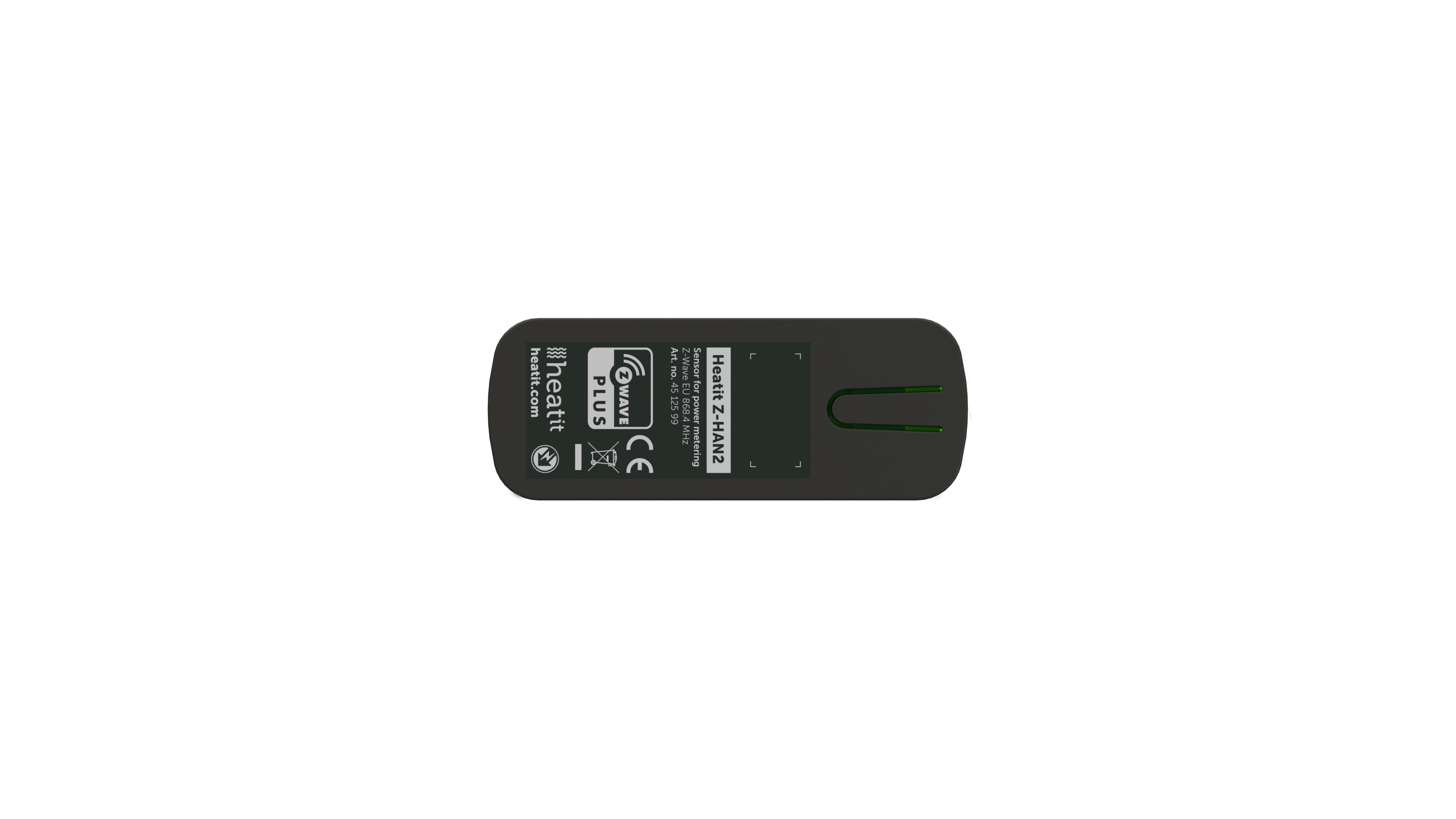
Product Recognition | |
|---|
Certification Number | ZC14-23070296 |
|---|
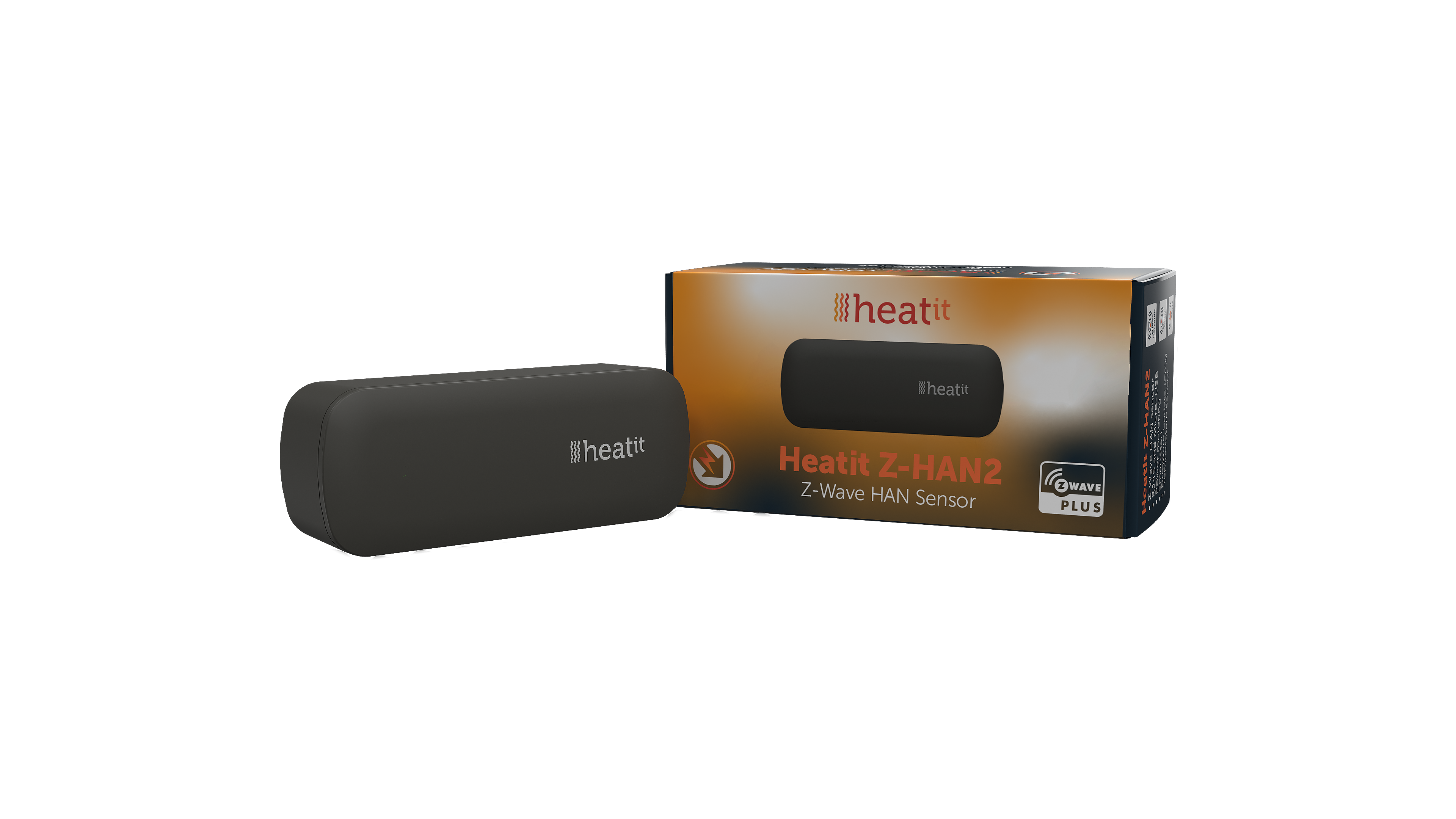
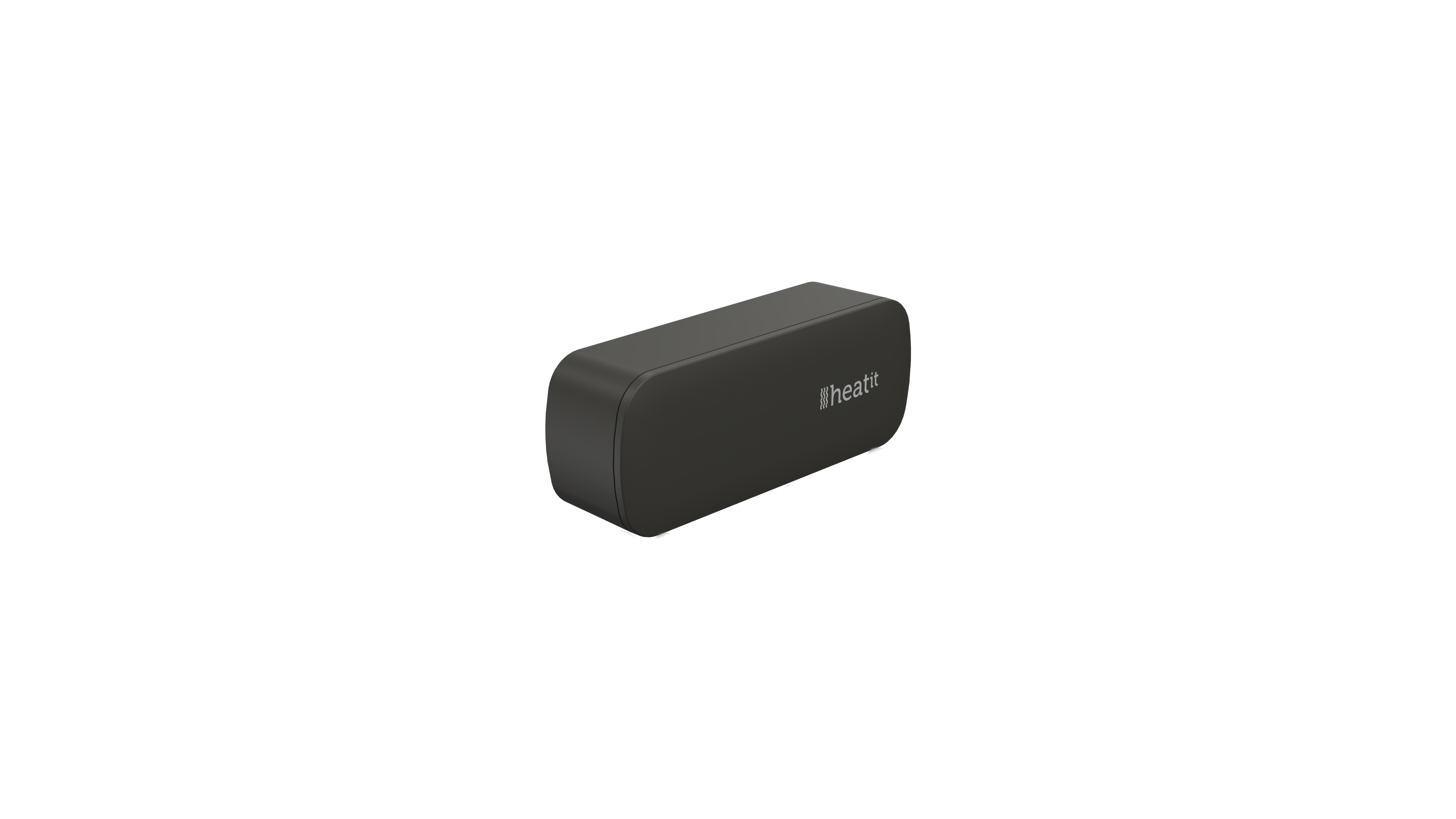
Name | Heatit Z-HAN2 |
|---|
Short Description | Heatit Z-HAN2 is a Z-Wave™ HAN sensor for AMS meters (Smart meters). Heatit Z-HAN2 works with HAN ports.
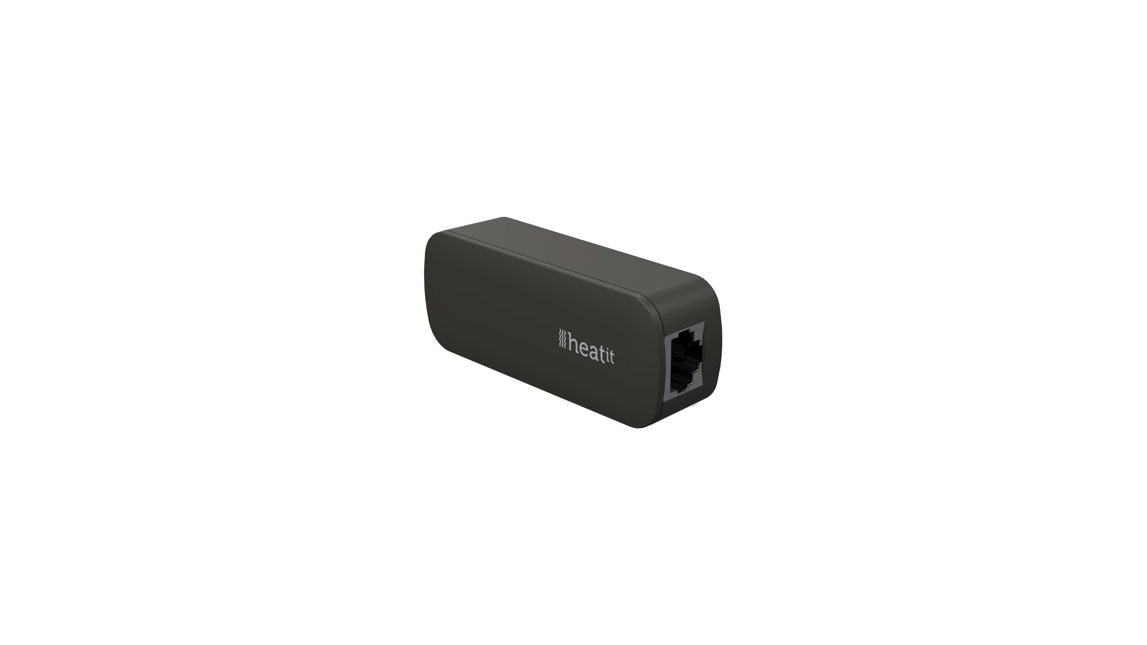
The Heatit Z-HAN2 is equipped with an RJ45 port for connecting the AMS meter. The Heatit Z-HAN2 can be powered through the RJ45 port by most AMS meters, but it also has a 5V micro USB input for external power supply. |
|---|
Long Description | Heatit Z-HAN2 is a Z-Wave™ HAN sensor for AMS meters (Smart meters). Heatit Z-HAN2 works with HAN ports.
The Heatit Z-HAN2 is equipped with an RJ45 port for connecting the AMS meter. The Heatit Z-HAN2 can be powered through the RJ45 port by most AMS meters, but it also has a 5V micro USB input for external power supply. |
|---|
Brand | Heatit |
|---|
Product Identifier | Z-HAN2 |
|---|
Product Line | Sensor |
|---|
OEM Version | HW: 01 FW: 01.00 |
|---|
Hardware Platform | EFR32ZG23A |
|---|
Z-Wave Version | 7.19.1 |
|---|
Library Type | END_NODE_ENHANCED_232 |
|---|
Device Type | Meter Sensor DT |
|---|
Role Type | ROLE_TYPE_SLAVE_ALWAYS_ON |
|---|
Manufacturer ID | 0x019B |
|---|
Product Type ID | 0x0062 |
|---|
Product ID | 0x6201 |
|---|
User Icon | 0x1700 |
|---|
Installer Icon | 0x1700 |
|---|
Frequency Plans | EU: 869.85MHz, 868.40MHz |
|---|
Categories | Sensors |
|---|
Countries / Regions | European Union |
|---|
Supported Command Classes | Identifier | Name | Key | Version |
|---|
COMMAND_CLASS_CONFIGURATION_V4 | Configuration V4 | 0x70 | 4 | COMMAND_CLASS_METER_V5 | Meter V5 | 0x32 | 5 | COMMAND_CLASS_SENSOR_MULTILEVEL_V11 | Multilevel Sensor V11 | 0x31 | 11 | COMMAND_CLASS_ASSOCIATION_V2 | Association V2 | 0x85 | 2 | COMMAND_CLASS_ASSOCIATION_GRP_INFO_V3 | Association Group Information (AGI) V3 | 0x59 | 3 | COMMAND_CLASS_DEVICE_RESET_LOCALLY | Device Reset Locally | 0x5A | 1 | COMMAND_CLASS_FIRMWARE_UPDATE_MD_V5 | Firmware Update Meta Data V5 | 0x7A | 5 | COMMAND_CLASS_INDICATOR_V3 | Indicator V3 | 0x87 | 3 | COMMAND_CLASS_MANUFACTURER_SPECIFIC_V2 | Manufacturer Specific V2 | 0x72 | 2 | COMMAND_CLASS_MULTI_CHANNEL_ASSOCIATION_V3 | Multi Channel Association V3 | 0x8E | 3 | COMMAND_CLASS_VERSION_V3 | Version V3 | 0x86 | 3 | COMMAND_CLASS_ZWAVEPLUS_INFO_V2 | Z-Wave Plus Info V2 | 0x5E | 2 | COMMAND_CLASS_SECURITY | Security 0 | 0x98 | 1 | COMMAND_CLASS_SECURITY_2 | Security 2 | 0x9F | 1 | COMMAND_CLASS_SUPERVISION | Supervision | 0x6C | 1 | COMMAND_CLASS_TRANSPORT_SERVICE_V2 | Transport Service V2 | 0x55 | 2 | COMMAND_CLASS_POWERLEVEL | Powerlevel | 0x73 | 1 |
|
|---|
S2 Classes | S2_AUTHENTICATED, S2_UNAUTHENTICATED |
|---|
Documents | Category | File |
|---|
Image_Product_Supplemental_3 | | Image_Product_Supplemental_4 | | Image_Product_Supplemental_5 | | Manual_English | |
|
|---|
Features | Feature | Values |
|---|
Color | | IP (Ingress Protection) Rated | |
|
|---|
Association Groups | Group Number | Maximum Nodes Supported | End Point ID | Group Name | Profile |
|---|
1 | 5 | 0 | Lifeline | 0x0001 | 2 | 5 | 0 | Meter Report | 0x3201 |
|
|---|
Configuration Parameters | Parameter Number | Name | Description | Format | Size | Min Value | Max Value | Default Value | Read-only |
|---|
1 | Meter report hysteresis for W | Set the Meter report hysteresis for Watts | 1 | 4 | 0 | 0 | 0x000000C8 | | 2 | Meter report hysteresis for V | Set the Meter report hysteresis for Volts | 1 | 2 | 0 | 0 | 0x0005 | | 3 | Meter report hysteresis for A | Set the Meter report hysteresis for Amps | 1 | 2 | 0 | 0 | 0x0014 | | 4 | Report interval for W | Set the wattage report interval | 1 | 2 | 0 | 0 | 0x000A | | 5 | Meter report interval for V and A | Set the meter report interval | 1 | 2 | 0 | 0 | 0x012C | | 6 | Temperature report interval | Set the Temperature report interval | 1 | 2 | 0 | 0 | 0x012C | | 7 | Temperature report hysteresis | Set the Temperature report hysteresis | 1 | 1 | 0 | 0 | 0x0A | | 8 | Sensor calibration | Manually calibrate the sensor ±6°C | 0 | 1 | 0 | 0 | 0x00 | | 9 | Serial | First half of AMS serial number | 1 | 4 | 0 | 0 | 0x66756E79 | Yes | 10 | Number | Last half of AMS serial number | 1 | 4 | 0 | 0 | 0x6D656D65 | Yes | 11 | Scaling factor | AMS multiplication factor | 1 | 2 | 0 | 0 | 0x0000 | |
|
|---|
Texts | ID | Description | Value |
|---|
8 | Where to find S2 DSK on product | The QR-Code is needed when including a device using S2 security or SmartStart. The DSK can be found in the QR-Code and is located;
• On the product.
• On the Quick Guide.
• On the gift box. | 1 | Classic Inclusion | The primary controller/gateway has a mode for adding devices. Please refer to your primary controller manual on how to set the primary controller in add mode. The device may only be added from the network if the primary controller is in add mode. When the device is removed from the network, it will NOT revert to factory settings.
An always listening node must be powered continuously and reside in a fixed position in the installation to secure the routing table. Adding the device within a 2 meters range from the gateway can minimize faults during the Interview process.
Standard (Manual)
Add mode is indicated on the device by a blinking green LED. It indicates this for 90 seconds until a timeout occurs, or until the module has been added to the network. Configuration mode can also be cancelled by performing the same procedure used for starting Configuration mode. USB cable must be used during add.
To start the configuration process, press the reset button 3 times in rapid sequence. The LED will light up in solid green for 3 seconds if add is successful. The device is now ready for use with default settings.
If inclusion fails, please perform a ”remove device” process and try again. If inclusion fails again, please see “Factory reset”. | 2 | Classic Exclusion | The primary controller/gateway has a mode for removing devices. Please refer to your primary controller manual on how to set the primary controller in remove mode. The device may only be removed from the network if the primary controller is in remove mode. When the device is removed from the network, it will NOT revert to factory settings.
An always listening node must be powered continuously and reside in a fixed position in the installation to secure the routing table. Removing the device within a 2 meters range from the gateway can minimize faults during the Interview process.
Standard (Manual)
Remove mode is indicated on the device by a blinking green LED. It indicates this for 90 seconds until a timeout occurs, or until the module has been removed from the network. Configuration mode can also be cancelled by performing the same procedure used for starting Configuration mode. USB cable must be used during remove.
To start the configuration process, press the reset button 3 times in rapid sequence. The LED will light up in solid green for 3 seconds if remove is successful. The device is now ready for use with default settings.
NB! When the device is removed from the gateway, the parameters are not reset. To reset the parameters, see Chapter ”Factory reset”.
If inclusion fails, please perform a ”remove device” process and try again. If inclusion fails again, please see “Factory reset”. | 5 | Factory Reset Procedure | Press and hold the reset button. After 3 seconds the LED will start to blink green. After 20 seconds the LED will start blinking green rapidly. You may now release the button. If reset was successful the LED will light up in solid green for 3 seconds.
USB cable must be used during factory reset.
Please use this procedure only when the network primary controller is missing or otherwise inoperable. |
|
|---|
Supported / Controlled Meter Types | Meter Type | Rate Type |
|---|
Electric meter | Import (consumed) |
|
|---|
Supported Multilevel Sensors | Multilevel Sensor Type |
|---|
Air temperature |
|
|---|
Supports NWI | Yes |
|---|
Supports Explorer Frames | Yes |
|---|
Supports SmartStart | Yes |
|---|
Radio Range Z-Wave (m) | 40 |
|---|