| Product Recognition | |
|---|
| Certification Number | ZC12-21060234 |
|---|
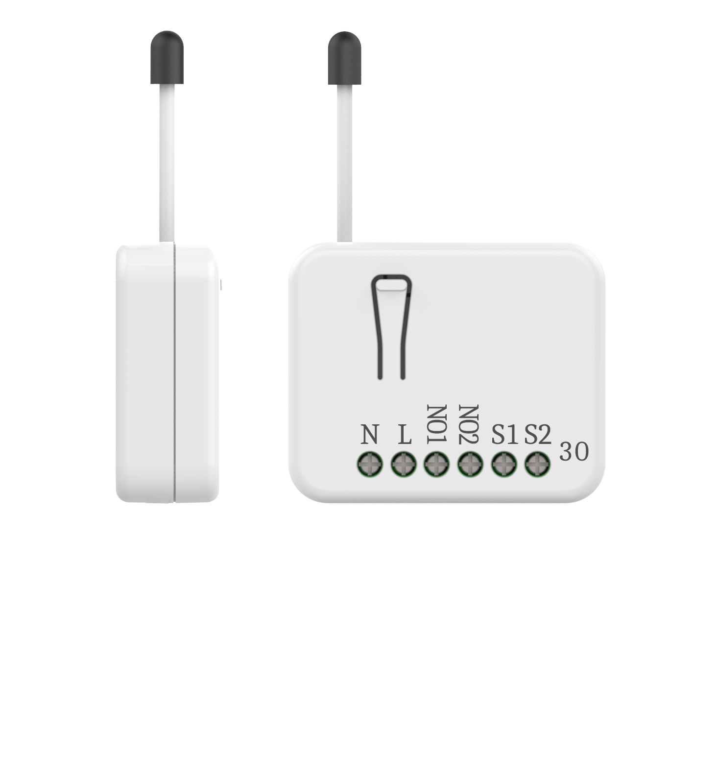
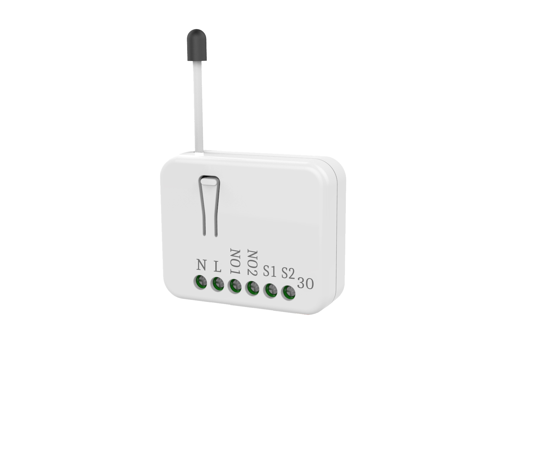
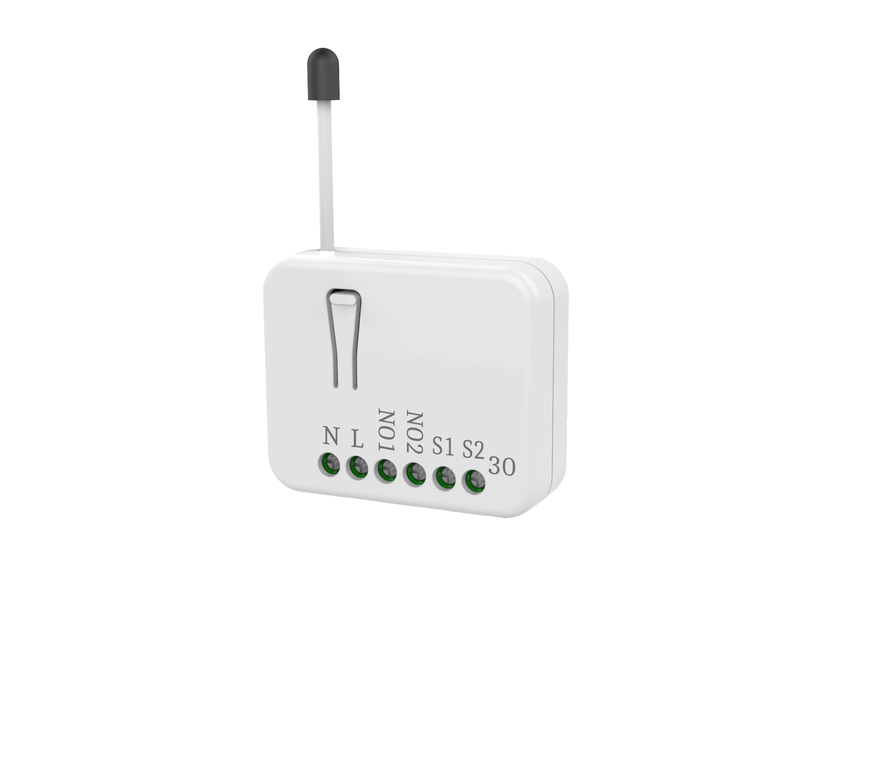
| Name | In Wall Dual relay switch module |
|---|
| Short Description | This in-wall dual relay switch module is a transceiver which is a Z-Wave Plus TM enabled device and is fully compatible with any Z-Wave TM enabled network. |
|---|
| Long Description | This in-wall dual relay switch module is a transceiver which is a Z-Wave Plus TM enabled device and is fully compatible with any Z-Wave TM enabled network. Mini size design let the module can easily hide itself into the wall box and that will be good for the house decoration.
There are many kind of application by using the module to switch AC power On and Off, one main application is the light control. The new smart relay calibration technology can reduce the inrush current caused by the load and let the module work perfectly with many kind of light like incandescent, fluorescent and LED light.
This in-wall switch module is able to detect Instant power wattage and overload current (7.5A with resistive load) of connected light or appliances. When detecting overload state, the Module will be disabled and its On/Off button will be lock-out of which LED will flash quickly. However, disconnect and re-connect the Module will reset its overload condition to normal status.
This product can be operated in any Z-Wave network with other Z-Wave certified devices from other manufacturers. All mains operated nodes within the network will act as repeaters regardless of vendor to increase reliability of the network. |
|---|
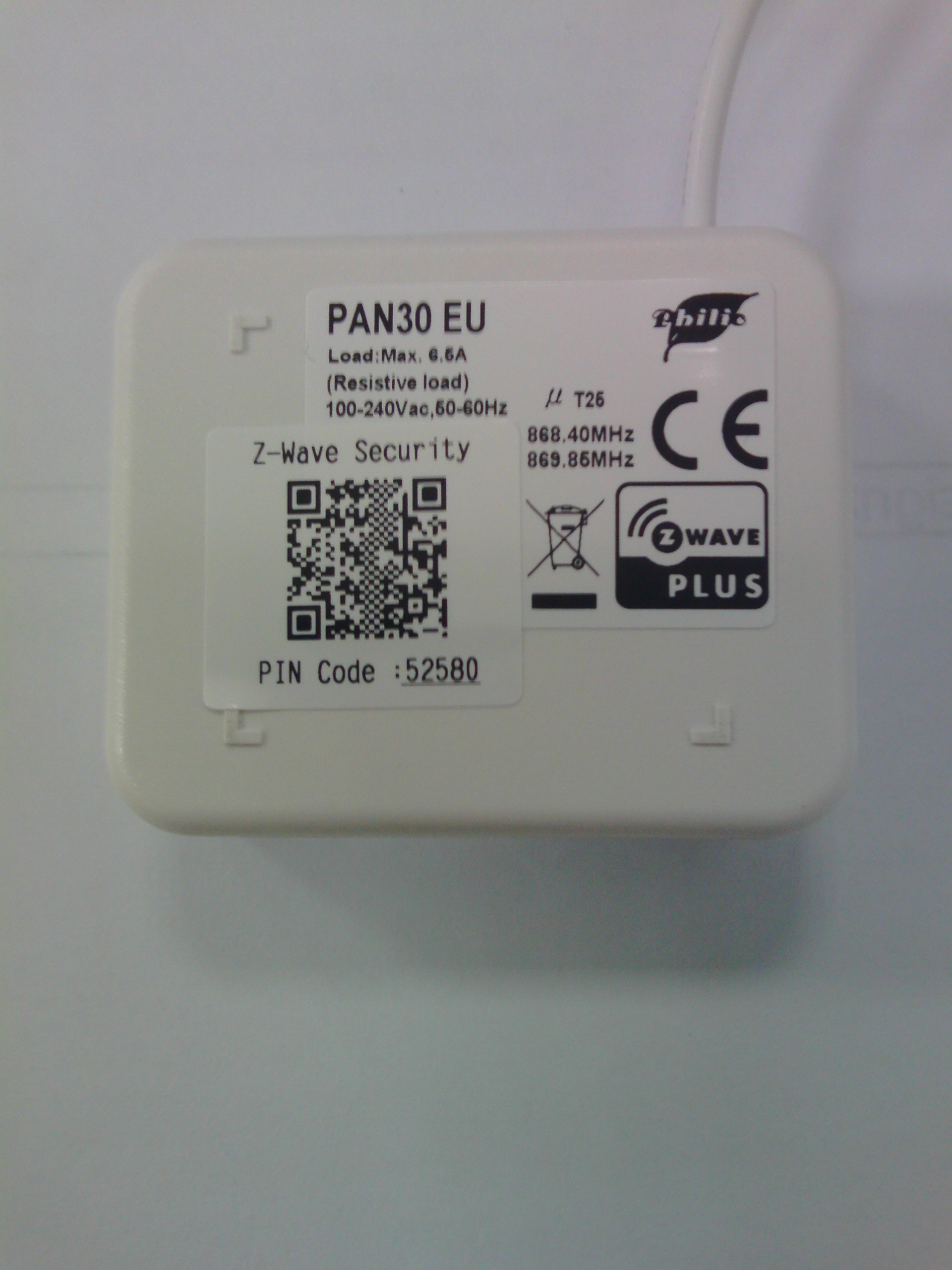
| Brand | Philio |
|---|
| Product Identifier | PAN30-1 |
|---|
| Product Line | Philio Z-Wave Products |
|---|
| OEM Version | HW: 1 FW: 1.01 |
|---|
| Hardware Platform | ZGM130 |
|---|
| Z-Wave Version | 7.15.1 |
|---|
| Library Type | SLAVE_ENHANCED_232 |
|---|
| Device Type | Binary Switch |
|---|
| Role Type | ROLE_TYPE_SLAVE_ALWAYS_ON |
|---|
| Manufacturer ID | 0x013C |
|---|
| Product Type ID | 0x0001 |
|---|
| Product ID | 0x0077 |
|---|
| User Icon | 0x0700 |
|---|
| Installer Icon | 0x0700 |
|---|
| Frequency Plans | EU: 869.85MHz, 868.40MHz |
|---|
| Categories | All Lighting Devices, On/Off Switches/Devices |
|---|
| Countries / Regions | European Union |
|---|
| Supported Command Classes | | Identifier | Name | Key | Version |
|---|
| COMMAND_CLASS_CONFIGURATION_V4 | Configuration V4 | 0x70 | 4 | | COMMAND_CLASS_SWITCH_BINARY_V2 | Switch Binary V2 | 0x25 | 2 | | COMMAND_CLASS_POWERLEVEL | Powerlevel | 0x73 | 1 | | COMMAND_CLASS_MULTI_CHANNEL_ASSOCIATION_V3 | Multi-Channel Association V3 | 0x8E | 3 | | COMMAND_CLASS_INDICATOR_V3 | Indicator V3 | 0x87 | 3 | | COMMAND_CLASS_SECURITY | Security S0 | 0x98 | 1 | | COMMAND_CLASS_TRANSPORT_SERVICE_V2 | Transport Service V2 | 0x55 | 2 | | COMMAND_CLASS_DEVICE_RESET_LOCALLY | Device Reset Locally | 0x5A | 1 | | COMMAND_CLASS_ZWAVEPLUS_INFO_V2 | Z-Wave Plus Info V2 | 0x5E | 2 | | COMMAND_CLASS_ASSOCIATION_V2 | Association V2 | 0x85 | 2 | | COMMAND_CLASS_FIRMWARE_UPDATE_MD_V5 | Firmware Update Meta-Data V5 | 0x7A | 5 | | COMMAND_CLASS_MULTI_CHANNEL_V4 | Multi-Channel V4 | 0x60 | 4 | | COMMAND_CLASS_ASSOCIATION_GRP_INFO_V3 | Association Group Information V3 | 0x59 | 3 | | COMMAND_CLASS_NOTIFICATION_V8 | Notification V8 | 0x71 | 8 | | COMMAND_CLASS_BASIC_V2 | Basic V2 | 0x20 | 2 | | COMMAND_CLASS_SECURITY_2 | Security S2 | 0x9F | 1 | | COMMAND_CLASS_METER_V5 | Meter V5 | 0x32 | 5 | | COMMAND_CLASS_VERSION_V3 | Version V3 | 0x86 | 3 | | COMMAND_CLASS_SUPERVISION | Supervision | 0x6C | 1 | | COMMAND_CLASS_MANUFACTURER_SPECIFIC_V2 | Manufacturer Specific V2 | 0x72 | 2 |
|
|---|
| S2 Classes | S2_UNAUTHENTICATED, S2_AUTHENTICATED |
|---|
| Documents | |
|---|
| Features | | Feature | Values |
|---|
| Switch Load Capacity Current | | | Color | | | Firmware Updatable | | Value |
|---|
| Updatable by Consumer by RF |
|
|
|---|
| Association Groups | | Group Number | Maximum Nodes Supported | End Point ID | Group Name | Profile | Description |
|---|
| 2 | 5 | 1 | Switch EP 1 | 0x0000 | For group 2, the Switch will report ON/OFF status of Relay1. | | 3 | 5 | 2 | Switch EP 2 | 0x0000 | For group 3, the Switch will report ON/OFF status of Relay2. | | 4 | 5 | 3 | Meter EP 3 | 0x3201 | For group 4, the Switch will report Instant Power Consumption (Watt) and Accumulated Power Consumption (KWh) of Relay1. | | 5 | 5 | 4 | Meter EP 4 | 0x3201 | For group 5, the Switch will report Instant Power Consumption (Watt) and Accumulated Power Consumption (KWh) of Relay2. | | 1 | 5 | 0 | Lifeline | 0x0001 | Group1 is called
Lifeline which support SWITCH_BINARY_REPORT、
METER_REPORT、NOTIFICATION_REPORT、INDICATOR_REPORT and
DEVICE_RESET_LOCALLY_NOTIFICATION. |
|
|---|
| Configuration Parameters | | Parameter Number | Name | Description | Format | Size | Min Value | Max Value | Default Value | Parameter Values |
|---|
| 2 | KWH Meter Report Period | If the setting is configured for 1hour (set value =6), the PAN30 will report its Accumulated Power Consumption (KW/h) every 1 hour to the node of correspond Group. The maximum interval to report its Accumulated Power Consumption (KW/h) is 227.55 days (10min*32767/1440=227.55 days). If the setting value is 0, the auto report function of meter KWh will be disabled. | 2 | 2 | 0 | 32767 | 6 | | From | To | Description |
|---|
| 0 | 0 | The auto report function of meter KWh will be disabled. | | 1 | 32767 | 6*10min= 1 hour |
| | 3 | Threshold of current for Load Caution | This is a warning when the current of load over the preset threshold value, if the setting value is 750, when the load current of Relay1 or Relay2 over this value, PAN30 will send current meter report to the node of correspond Group, the Range of the setting value is from 10 to 750, and the default value is 750. | 2 | 2 | 10 | 750 | 750 | | From | To | Description |
|---|
| 10 | 750 | 750*0.01A = 7.5A |
| | 4 | Threshold of KWh for Load Caution | This is a warning when the KWh of load over the preset threshold value, If the setting value is 10000, when the Accumulated Power Consumption of Relay1 or Relay2 over this value, PAN30 will send KWh Meter Report command to the node of correspond Group, minimum value is 1KWh and default value is 10000 kWh. | 2 | 2 | 1 | 10000 | 10000 | | From | To | Description |
|---|
| 1 | 10000 | 1KWh ~ 10000KWh |
| | 6 | Restore switch state mode | Whenever the AC power return from lost, PAN30 will restore the switch state which could be SWITCH OFF、LAST SWITCH STATE、SWITCH ON. The default setting is LAST SWITCH STATE. | 3 | 1 | 0 | 2 | 1 | | From | To | Description |
|---|
| 0 | 0 | Switch off | | 1 | 0 | Last switch state | | 2 | 0 | Switch on |
| | 5 | External switch mode | Manual switch S1 and S2 can set to Edge mode or Pulse mode or Edge-Toggle mode, default value is Edge mode. | 3 | 1 | 1 | 3 | 1 | | From | To | Description |
|---|
| 1 | 0 | Edge mode | | 2 | 0 | Pulse mode | | 3 | 0 | Edge-Toggle mode |
| | 7 | Watt differential report mode | It will trigger a Watt report when the variation of watt value is over the preset percentage. | 3 | 1 | 0 | 4 | 1 | | From | To | Description |
|---|
| 0 | 0 | The function of Watt differential report will be disabled. | | 1 | 0 | 5% | | 2 | 0 | 10% | | 3 | 0 | 15% | | 4 | 0 | 20% |
| | 1 | Watt Meter Report Period | If the setting is configured for 1hour (set value =720), the PAN30 will report its instant power consumption every 1 hour to the node of correspond Group. The maximum interval to report its instant power consumption is 45 hours (5s*32767/3600=45hr). If the setting value is 0, the auto report function of meter Watt will be disabled. | 2 | 2 | 0 | 32767 | 720 | | From | To | Description |
|---|
| 0 | 0 | The auto report function of meter Watt will be disabled. | | 1 | 32767 | 720*5s=3600s= 1 hour |
|
|
|---|
| Texts | | ID | Description | Value |
|---|
| 8 | Where to find S2 DSK on product | 1. To initiate the SmartSart process, please type in the first five digits of DSK string or scan the QR code. The QR Code can be found on PAN30 or in the box. Ex: DSK: 18112-24021-58001-62259-57092- 27453-08187-47408
2. PAN30 is supported with SmartStart, it can be added to Z-Wave™ network by scanning the Z-Wave™ QR code on the product.
3. Without further actions, PAN30 will be automatically included in a certified Z-Wave™ Controller with SmartStart inclu-
sion ability in 10 minutes after it turned on. | | 5 | Factory Reset Procedure | 1. Pressing INCLUDE_BUTTON three times within 2 seconds will enter inclusion mode.
2. Within 1 second, press On/Off button again for 5 seconds.
3. IDs are excluded. | | 1 | Classic Inclusion | 1. Put your Z-Wave controller into inclusion mode by following the instructions provided by the controller manufacturer.
2. Pressing INCLUDE_BUTTON three times within 2 seconds will enter inclusion mode. | | 2 | Classic Exclusion | 1. Put your Z-Wave controller into exclusion mode by following the instructions provided by the controller manufacturer.
2. Pressing INCLUDE_BUTTON three times within 2 seconds will enter exclusion mode.
3. Node ID has been excluded. |
|
|---|
| Supported / Controlled Meter Types | | Meter Type | Rate Type | Description |
|---|
| Electric meter | Import | Electric Meter Consumption |
|
|---|
| Supported Notification Types | | Notification Type | Event / State |
|---|
| Power Management | (Refer to parameters): State idle | | Power Management | Over-load status: Over-load detected |
|
|---|
| Supports NWI | Yes |
|---|
| Supports Explorer Frames | Yes |
|---|
| Supports SmartStart | Yes |
|---|