Product Recognition | |
|---|
Certification Number | ZC10-17055608 |
|---|
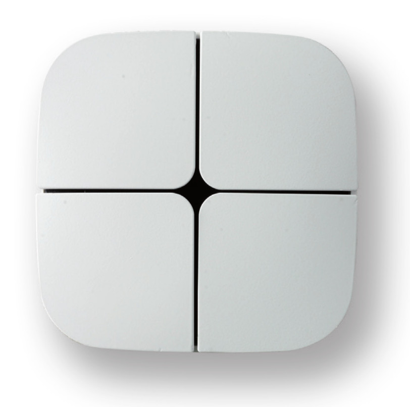
Name | Push button Eelecta |
|---|
Short Description | Eelecta Homepad is a 4 channels pushbutton with 1 integrated 10A 250V relay. Equipped with 5 Led for buttons feedback and relay status. |
|---|
Long Description | Eelecta Homepad is a 4 channels pushbutton with 1 integrated 10A 250V relay. Equipped with 5 Led for buttons feedback and relay status. The device can control electrical loads or dimmerable actuators. The module is controlled either through the Z-Wave network or a simple switch. Designed to replace your conventional switch and control the connected load. The device works with 3-wires system, so neutral is required. |
|---|
Brand | Eelectron SpA |
|---|
Product Identifier | PB41AxxZWE |
|---|
OEM Version | HW: 1 FW: 1.07 |
|---|
Hardware Platform | ZM5202 |
|---|
Z-Wave Version | 6.51.10 |
|---|
Library Type | SLAVE_ENHANCED_232 |
|---|
Device Type | On/Off Power Switch |
|---|
Role Type | ROLE_TYPE_SLAVE_ALWAYS_ON |
|---|
Manufacturer ID | 0x031F |
|---|
Product Type ID | 0x0001 |
|---|
Product ID | 0x1030 |
|---|
User Icon | 0x0700 |
|---|
Installer Icon | 0x0700 |
|---|
Frequency Plans | EU: 869.85MHz, 868.40MHz |
|---|
Categories | All Lighting Devices, On/Off Switches/Devices |
|---|
Countries / Regions | European Union |
|---|
Supported Command Classes | Identifier | Name | Key | Version |
|---|
COMMAND_CLASS_POWERLEVEL | Powerlevel | 0x73 | 1 | COMMAND_CLASS_MULTI_CHANNEL_ASSOCIATION_V3 | Multi-Channel Association V3 | 0x8E | 3 | COMMAND_CLASS_SWITCH_BINARY | Switch Binary | 0x25 | 1 | COMMAND_CLASS_BASIC | Basic | 0x20 | 1 | COMMAND_CLASS_CONFIGURATION | Configuration | 0x70 | 1 | COMMAND_CLASS_VERSION_V2 | Version V2 | 0x86 | 2 | COMMAND_CLASS_DEVICE_RESET_LOCALLY | Device Reset Locally | 0x5A | 1 | COMMAND_CLASS_ZWAVEPLUS_INFO_V2 | Z-Wave Plus Info V2 | 0x5E | 2 | COMMAND_CLASS_ASSOCIATION_V2 | Association V2 | 0x85 | 2 | COMMAND_CLASS_ASSOCIATION_GRP_INFO | Association Group Info | 0x59 | 1 | COMMAND_CLASS_MANUFACTURER_SPECIFIC | Manufacturer Specific | 0x72 | 1 | COMMAND_CLASS_FIRMWARE_UPDATE_MD_V2 | Firmware Update Meta-Data V2 | 0x7A | 2 |
|
|---|
Controlled Command Classes | Identifier | Name | Key | Version |
|---|
COMMAND_CLASS_SWITCH_MULTILEVEL | Switch Multilevel | 0x26 | 1 | COMMAND_CLASS_SWITCH_BINARY | Switch Binary | 0x25 | 1 | COMMAND_CLASS_DEVICE_RESET_LOCALLY | Device Reset Locally | 0x5A | 1 |
|
|---|
Documents | Category | Description | File |
|---|
Manual_Primary_Lang | Product or Owner's Manual | |
|
|---|
Features | Feature | Values |
|---|
Firmware Updatable | Value |
|---|
Updatable by Consumer by RF |
| Switch Load Capacity Current | | Neutral Wire Required | | Switch Type | Value |
|---|
Push Button with Indicator |
| Electric Load Type | Value |
|---|
Incandescent | Fluorescent | MLV (Magnetic) | ELV (Electronic) | LED | Inductive (e.g. Motor) |
|
|
|---|
Association Groups | Group Number | Maximum Nodes Supported | End Point ID | Description |
|---|
1 | 8 | 0 | Z-Wave Plus Lifeline; Switch Binary Report or Device Reset Locally Notification are sent to the nodes in this association group. | 2 | 8 | 0 | On/Off control; Switch Binary/Push Button Set. | 3 | 8 | 0 | Dimming Control; Dimmer Set. |
|
|---|
Configuration Parameters | Parameter Number | Name | Description | Format | Size | Min Value | Max Value | Default Value | Parameter Values |
|---|
1 | Local load control | Defines which button is related to the control of the local load. | 0 | 1 | 0 | 0 | 1 | From | To | Description |
|---|
4 | 0 | Relay controlled by button 4 | 2 | 0 | Relay controlled by button 2 | 1 | 0 | Relay controlled by button 1 | 3 | 0 | Relay controlled by button 3 | 0 | 0 | None of the buttons controls the local load |
| 2 | Control of devices linked with groups 2,3,4,5,6,7,8,9 | Defines in which cases the control of the linked devices will be activated with a "click" of a configured button. In order to control devices linked to a group these devices have to belong to this group. | 0 | 1 | 0 | 0 | 3 | From | To | Description |
|---|
1 | 0 | The possible associations will ignored and associated devices will be not controlled | 2 | 0 | The associated devices will always be controlled by a click of one of the four buttons | 3 | 0 | The associated devices will be controlled only from those buttons that aren’t associated to the local load |
| 5 | LED Feedback | Defines which events trigger LED feedback. The value to be entered for this parameter it’s calculated as the sum of the values associated with the individual entities indicated in table. | 0 | 1 | 0 | 0 | 3 | From | To | Description |
|---|
1 | 0 | LED reporting state of the Relay | 2 | 0 | Feedback on press button | 4 | 0 | Feedback on notification received from Remote devices |
| 60 | Status at Power on | Status after device restart. | 0 | 1 | 0 | 0 | 4 | From | To | Description |
|---|
1 | 0 | Local Relay close | 2 | 0 | Local Relay open | 4 | 0 | Keep status before power down |
| 61 | Configuration Reset | Define which parameters will be set to Factory Defaults. | 0 | 1 | 0 | 0 | 4 | From | To | Description |
|---|
1 | 0 | All and only the associations are reset | 2 | 0 | The associations are preserved while all other parameters of configuration will be reset to Factory defaults, except this one that remains unchanged | 3 | 0 | Device will be restarted | 4 | 0 | No action is carried out |
|
|
|---|
Texts | ID | Description | Value |
|---|
1 | Inclusion | The device supports both the mechanism “Network Wide Inclusion” (which offers the possibility of inclusion in a network even though the device is not directly related to the controller) and the “Normal Inclusion”.
If the device is in factory default configuration, the single click of one of the buttons, starts the “Network Wide Inclusion” process that lasts for a time between 15 and 30 seconds. | 5 | Factory Reset | To restore the device to the original factory configuration one of the following methods can be adopted:
1. Remove the device from the Z-Wave network using the controller;
2. Disconnect the device from the main power supply and reconnect it pressing consecutively six times one of its buttons within 1 minute from the device start. Please use this procedure only when the network primary controller is missing or otherwise inoperable.
INFO: Upon removal, if the device (node) is included in a network it notifies to other devices its removal (Device Reset Locally Notification).
If the device receives a notification of removal from part of another device in the network, the associations of the latter will be removed. | 2 | Exclusion | Only a controller has the ability to remove a device from the Z-Wave network where is included.
PB41AxxZWE is compatible with all certified Z-Wave controllers.
The exclusion procedure must be initiated by the controller and ended on the device that can be removed with the triple consecutive pressing of one of the buttons on the device. |
|
|---|
Supports NWI | Yes |
|---|
Supports Explorer Frames | Yes |
|---|
Radio Range Z-Wave (m) | 40 |
|---|