| Product Recognition | |
|---|
| Certification Number | ZC12-21020178 |
|---|
| Name | Radio I/O Modul |
|---|
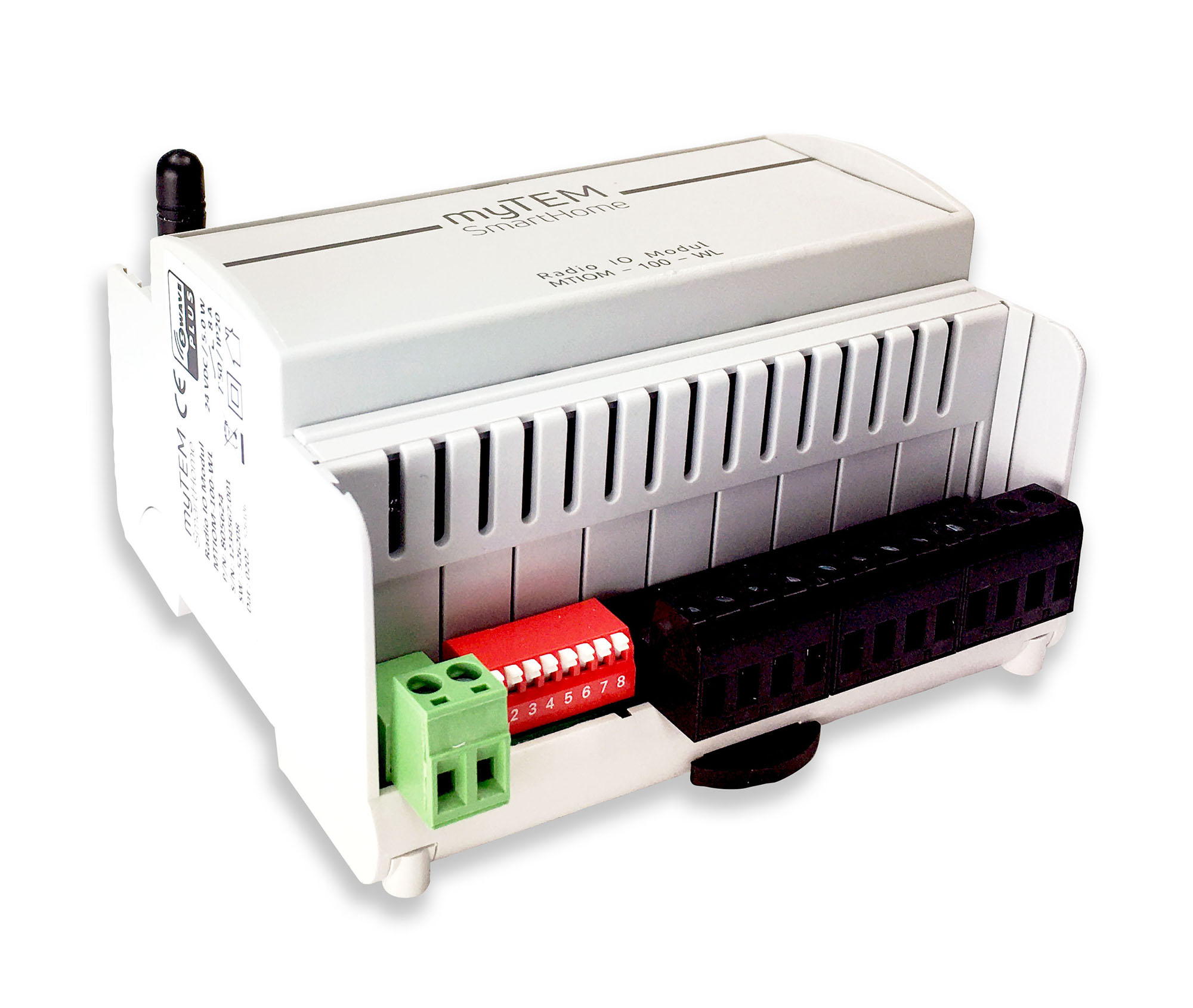
| Short Description | The Radio IO Modul MTIOM-100-WL is a universal, Z-Wave compatible module from myTEM for extending your smart home system with additional inputs and outputs. |
|---|
| Long Description | The Radio IO Modul MTIOM-100-WL is a universal, Z-Wave compatible module from myTEM for extending your smart home system with additional inputs and outputs. It is a Z-Wave device of the type Binary Switch for the use in Europe / Switzerland.
Main use is for:
- Switching of lights
- Switching of single-phase fan motors
- Switching of electric blinds or similar shading devices
- Operation by means of buttons, sensors via the central server
Functions:
- Supply voltage 24 VDC ± 10%
- Communication via Z-Wave mesh network
- 6 digital inputs 24 VDC (DI1 – DI6) for e.g. external switches
- 24 VDC power supply, 100 mA, for the digital inputs DI1 – DI6 (VDIout)
- 4 analog inputs (AI1 – AI4), which can be used for 0-10 VDC or NTC-, PTC- or PT1000 sensors. Analog inputs can also be used as digital inputs 24 VDC.
- 6 digital outputs with potential-free, relay 8 A, 250 VAC
- Manual positions of the outputs via DIP switch for easy commissioning
- The device is installed in a control cabinet, mounted on a 35 mm DIN rail |
|---|
| Brand | myTEM SmartHome |
|---|
| Product Identifier | MTIOM-100-WL |
|---|
| Product Line | myTEM SmartHome |
|---|
| OEM Version | HW: 0 FW: 1.00:00.07 |
|---|
| Hardware Platform | ZGM130 |
|---|
| Z-Wave Version | 7.13.2 |
|---|
| Library Type | SLAVE_ENHANCED_232 |
|---|
| Device Type | Binary Switch |
|---|
| Role Type | ROLE_TYPE_SLAVE_ALWAYS_ON |
|---|
| Manufacturer ID | 0x034E |
|---|
| Product Type ID | 0x0001 |
|---|
| Product ID | 0x000A |
|---|
| User Icon | 0x0800 |
|---|
| Installer Icon | 0x0800 |
|---|
| Frequency Plans | EU: 869.85MHz, 868.40MHz |
|---|
| Categories | Sensors, All Lighting Devices, On/Off Switches/Devices, HVAC |
|---|
| Countries / Regions | European Union |
|---|
| Supported Command Classes | | Identifier | Name | Key | Version |
|---|
| COMMAND_CLASS_CONFIGURATION_V4 | Configuration V4 | 0x70 | 4 | | COMMAND_CLASS_SWITCH_BINARY_V2 | Switch Binary V2 | 0x25 | 2 | | COMMAND_CLASS_POWERLEVEL | Powerlevel | 0x73 | 1 | | COMMAND_CLASS_MULTI_CHANNEL_ASSOCIATION_V3 | Multi-Channel Association V3 | 0x8E | 3 | | COMMAND_CLASS_INDICATOR_V3 | Indicator V3 | 0x87 | 3 | | COMMAND_CLASS_TRANSPORT_SERVICE_V2 | Transport Service V2 | 0x55 | 2 | | COMMAND_CLASS_DEVICE_RESET_LOCALLY | Device Reset Locally | 0x5A | 1 | | COMMAND_CLASS_ZWAVEPLUS_INFO_V2 | Z-Wave Plus Info V2 | 0x5E | 2 | | COMMAND_CLASS_ASSOCIATION_V2 | Association V2 | 0x85 | 2 | | COMMAND_CLASS_FIRMWARE_UPDATE_MD_V5 | Firmware Update Meta-Data V5 | 0x7A | 5 | | COMMAND_CLASS_MULTI_CHANNEL_V4 | Multi-Channel V4 | 0x60 | 4 | | COMMAND_CLASS_ASSOCIATION_GRP_INFO_V3 | Association Group Information V3 | 0x59 | 3 | | COMMAND_CLASS_NOTIFICATION_V8 | Notification V8 | 0x71 | 8 | | COMMAND_CLASS_BASIC_V2 | Basic V2 | 0x20 | 2 | | COMMAND_CLASS_SECURITY_2 | Security S2 | 0x9F | 1 | | COMMAND_CLASS_SENSOR_MULTILEVEL_V11 | Sensor Multilevel V11 | 0x31 | 11 | | COMMAND_CLASS_VERSION_V3 | Version V3 | 0x86 | 3 | | COMMAND_CLASS_SUPERVISION | Supervision | 0x6C | 1 | | COMMAND_CLASS_MANUFACTURER_SPECIFIC_V2 | Manufacturer Specific V2 | 0x72 | 2 |
|
|---|
| S2 Classes | S2_UNAUTHENTICATED, S2_AUTHENTICATED |
|---|
| Documents | |
|---|
| Features | | Feature | Values |
|---|
| Electric Load Type | | | Loads Controlled | | | Z-Wave Scene Type | |
|
|---|
| Association Groups | | Group Number | Maximum Nodes Supported | End Point ID | Group Name | Profile | Description |
|---|
| 1 | 5 | 0 | Lifeline | 0x0001 | (Lifeline group) Root: Notification Report System::Heartbeat triggered periodically, Notification Report Power Management::Power has bin applied triggered upon start-up, Device Reset Locally triggered upon set to factory default.
EP7 - EP12: Notification Report System::Digital input open triggered when digital input 1 - 6 resp. change from 24V applied to open, Notification Report System::Digital input high state triggered when digital input 1 - 6 resp. change from open to 24V applied.
EP13 - EP17: Multilevel Sensor Report triggered periodically or on value change of analog input 1 - 4 resp.
EP13 - EP17: Multilevel Sensor Supported Report triggered when type of analog input 1 - 4 resp. is changed by configuration parameter. |
|
|---|
| Configuration Parameters | | Parameter Number | Name | Description | Format | Size | Min Value | Max Value | Default Value | Parameter Values |
|---|
| 1 | Heartbeat rate [min] | see manual | 2 | 2 | 1 | 1440 | 60 | | From | To | Description |
|---|
| 1 | 1440 | Value tells at what interval [min] Heartbeat will be sent |
| | 8 | DI 4 send enable | see manual | 2 | 2 | 0 | 2 | 0 | | From | To | Description |
|---|
| 0 | 0 | Notifications for DI 4 are disabled | | 1 | 1 | Binary Sensor Report for DI 4 is enabled | | 2 | 2 | Central Scene Report for DI 4 is enabled |
| | 5 | DI 2 send interval [min] | see manual | 2 | 2 | 1 | 1200 | 50 | | From | To | Description |
|---|
| 1 | 1200 | Value tells at what interval [0.1min] notification for DI 2 will we sent |
| | 7 | DI 3 send interval[min] | see manual | 2 | 2 | 1 | 1200 | 50 | | From | To | Description |
|---|
| 1 | 1200 | Value tells at what interval [0.1min] notification for DI 3 will we sent |
| | 9 | DI 4 send interval [min] | see manual | 2 | 2 | 1 | 1200 | 50 | | From | To | Description |
|---|
| 1 | 1200 | Value tells at what interval [0.1min] notification for DI 4 will we sent |
| | 11 | DI 5 send interval [min] | see manual | 2 | 2 | 1 | 1200 | 50 | | From | To | Description |
|---|
| 1 | 1200 | Value tells at what interval [0.1min] notification for DI 5 will we sent |
| | 17 | AI 1 send delta temp [K] | see manual | 1 | 2 | 1 | 100 | 5 | | From | To | Description |
|---|
| 1 | 100 | Value tells at what temperature difference [0.1K]for AI 1 will be sent |
| | 23 | AI 2 send delta volt [V] | see manual | 2 | 2 | 1 | 100 | 5 | | From | To | Description |
|---|
| 1 | 100 | Value tells at what voltage difference [0.1V]for AI 2 will be sent |
| | 24 | AI 3 send enable | see manual | 2 | 2 | 0 | 1 | 0 | | From | To | Description |
|---|
| 0 | 0 | Sending AI 3 values disabled | | 1 | 1 | Sending AI 3 values enabled |
| | 25 | AI 3 sensor select | see manual | 2 | 2 | 0 | 5 | 0 | | From | To | Description |
|---|
| 0 | 0 | Configure AI 3 for NTC 5k Ohm thermistor | | 1 | 1 | Configure AI 3 for NTC 10k Ohm thermistor | | 2 | 2 | Configure AI 3 for PTC 1k Ohm thermistor | | 3 | 3 | Configure AI 3 for PT1000 thermistor | | 4 | 4 | Configure AI 3 for 0 - 10V sensor | | 5 | 5 | Configure AI 3 for digital input |
| | 3 | DI 1 send interval [min] | see manual | 2 | 2 | 1 | 1200 | 50 | | From | To | Description |
|---|
| 1 | 1200 | Value tells at what interval [0.1min] notification for DI 1 will we sent |
| | 10 | DI 5 send enable | see manual | 2 | 2 | 0 | 2 | 0 | | From | To | Description |
|---|
| 1 | 1 | Binary Sensor Report for DI 5 is enabled | | 0 | 0 | Notifications for DI 5 are disabled | | 2 | 2 | Central Scene Report for DI 5 is enabled |
| | 2 | DI 1 send enable | see manual | 2 | 2 | 0 | 2 | 0 | | From | To | Description |
|---|
| 0 | 0 | Notifications for DI 1 are disabled | | 1 | 1 | Binary Sensor Report for DI 1 is enabled | | 2 | 2 | Central Scene Report for DI 1 is enabled |
| | 6 | DI 3 send enable | see manual | 2 | 2 | 0 | 2 | 0 | | From | To | Description |
|---|
| 0 | 0 | Notifications for DI 3 are disabled | | 1 | 1 | Binary Sensor Report for DI 3 is enabled | | 2 | 2 | Central Scene Report for DI 3 is enabled |
| | 4 | DI 2 send enable | see manual | 2 | 2 | 0 | 2 | 0 | | From | To | Description |
|---|
| 0 | 0 | Notifications for DI 2 are disabled | | 1 | 1 | Binary Sensor Report for DI 2 is enabled | | 2 | 2 | Central Scene Report for DI 2 is enabled |
| | 31 | AI 4 send interval [min] | see manual | 2 | 2 | 1 | 1200 | 50 | | From | To | Description |
|---|
| 1 | 1200 | Value tells at what interval [0.1min] sensor values for AI 4 will be sent |
|
|
|---|
| Texts | | ID | Description | Value |
|---|
| 2 | Classic Exclusion | Manual inclusion/exclusion (“Add/Remove”)
If the myTEM Radio IO Modul Floor shows status “Add”, the “Remove” can be performed with any controller in the network or with the help of a new controller. However, it is recommended to use the primary controller of the previous network unless it is no longer available or damaged.
“Remove” deletes the memory chip, including all Z-Wave network settings.
1. Activate the “Add” or “Remove” mode on your controller.
2. Press the button (T) four times in quick succession to start include / exclude (“Add / Remove”).
When the device is in the “Add” mode, the LED flashes green.
When finished, the new status is:
Add: The LED 2 lights up briefly in green
Remove: The LED 2 lights up briefly in red | | 5 | Factory Reset Procedure | Please use this procedure only when the network primary controller is missing or otherwise inoperable.
Power-up the device and then press the button (T) for 10 seconds.
Reset: The LED lights up briefly in red
The device reset deletes the memory chip, including all Z-Wave network settings. | | 8 | Where to find S2 DSK on product | The DSK label (QR code) is located on the long side of the housing. | | 1 | Classic Inclusion | Manual inclusion/exclusion (“Add/Remove”)
1. Activate the “Add” or “Remove” mode on your controller.
2. Press the button (T) four times in quick succession to start include / exclude (“Add / Remove”).
When the device is in the “Add” mode, the LED flashes green.
When finished, the new status is:
Add: The LED 2 lights up briefly in green
Remove: The LED 2 lights up briefly in red |
|
|---|
| Supported Notification Types | | Notification Type | Event / State |
|---|
| Power Management | Power status: Power has been applied | | System | Heartbeat |
|
|---|
| Supported Multilevel Sensors | | Multilevel Sensor Type |
|---|
| Air temperature | | Voltage |
|
|---|
| Supports NWI | Yes |
|---|
| Supports Explorer Frames | Yes |
|---|
| Supports SmartStart | Yes |
|---|