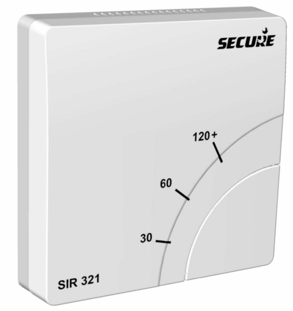
Product Recognition | |
|---|
Certification Number | ZC10-20127001 |
|---|
Name | SIR 321 |
|---|
Short Description | SIR 321 is a Z-Wave Plus countdown timer having one relay and support of duration base schedule that can be used to control any electrical appliances, it can measure and report room temperature. |
|---|
Long Description | SIR 321 is a Z-Wave Plus countdown timer with one relay and support of duration base schedule that can be used to control any electrical appliances rated up to 3 kW.
With an external temperature sensor, SIR 321 can measure room temperature and send temperature report on regular interval or delta temperature change as per configuration.
It forms part of central heating control system, it can be operated by any third party controllers using ‘Binary Switch command class’ commands.
SIR 321 will act as a repeater once added into the Z- Wave network, providing an alternative communication route for units which otherwise would not be within communication distance of each other.
SIR 321 has a fail-safe mode where by the relay is turned OFF if another 'Binary switch SET' or 'Basic SET' command has not been received within 60 minutes. |
|---|
Brand | Secure |
|---|
Product Identifier | MAX10Y-376 |
|---|
Product Line | Heating and Controls |
|---|
OEM Version | HW: 1 FW: 1.00 |
|---|
Hardware Platform | ZM5202 |
|---|
Z-Wave Version | 6.82.01 |
|---|
Library Type | SLAVE_ROUTING |
|---|
Device Type | On/Off Power Switch |
|---|
Role Type | ROLE_TYPE_SLAVE_ALWAYS_ON |
|---|
Manufacturer ID | 0x0059 |
|---|
Product Type ID | 0x0010 |
|---|
Product ID | 0x0003 |
|---|
User Icon | 0x0700 |
|---|
Installer Icon | 0x0700 |
|---|
Frequency Plans | EU: 869.85MHz, 868.40MHz |
|---|
Categories | All Lighting Devices, On/Off Switches/Devices |
|---|
Countries / Regions | European Union |
|---|
Supported Command Classes | Identifier | Name | Key | Version |
|---|
COMMAND_CLASS_POWERLEVEL | Powerlevel | 0x73 | 1 | COMMAND_CLASS_SCHEDULE | Schedule | 0x53 | 1 | COMMAND_CLASS_SWITCH_BINARY | Switch Binary | 0x25 | 1 | COMMAND_CLASS_BASIC | Basic | 0x20 | 1 | COMMAND_CLASS_CONFIGURATION | Configuration | 0x70 | 1 | COMMAND_CLASS_TRANSPORT_SERVICE_V2 | Transport Service V2 | 0x55 | 2 | COMMAND_CLASS_VERSION_V2 | Version V2 | 0x86 | 2 | COMMAND_CLASS_DEVICE_RESET_LOCALLY | Device Reset Locally | 0x5A | 1 | COMMAND_CLASS_ZWAVEPLUS_INFO_V2 | Z-Wave Plus Info V2 | 0x5E | 2 | COMMAND_CLASS_ASSOCIATION_V2 | Association V2 | 0x85 | 2 | COMMAND_CLASS_ASSOCIATION_GRP_INFO_V3 | Association Group Information V3 | 0x59 | 3 | COMMAND_CLASS_SECURITY_2 | Security S2 | 0x9F | 1 | COMMAND_CLASS_SENSOR_MULTILEVEL_V11 | Sensor Multilevel V11 | 0x31 | 11 | COMMAND_CLASS_SUPERVISION | Supervision | 0x6C | 1 | COMMAND_CLASS_MANUFACTURER_SPECIFIC_V2 | Manufacturer Specific V2 | 0x72 | 2 |
|
|---|
S2 Classes | S2_UNAUTHENTICATED |
|---|
Documents | Category | Description | File |
|---|
Manual_Primary_Lang | Product Manual in English | |
|
|---|
Features | Feature | Values |
|---|
Color | | Switch Load Capacity Watts | | Firmware Updatable | | IP (Ingress Protection) Rated | | Switch Load Capacity Current | Value |
|---|
13 Amps resistive or 3 Amps inductive |
|
|
|---|
Association Groups | Group Number | Maximum Nodes Supported | End Point ID | Group Name | Profile | Description |
|---|
3 | 4 | 0 | Air Temperature | 0x3101 | Send Multilevel Sensor Report to associated nodes in regular interval or delta change in temperature as per configuration. | 2 | 4 | 0 | Schedule Report | 0x0000 | Send Schedule Report to associated nodes, whenever the schedule status changed by any mean (i.e. through RF or boost button). | 1 | 1 | 0 | Lifeline | 0x0001 | (Lifeline group) Send Switch Binary report whenever relay state change,
Send Schedule Report whenever the schedule status change,
Send Multilevel Sensor report in regular interval or delta change in temperature as per configuration. |
|
|---|
Configuration Parameters | Parameter Number | Name | Description | Format | Size | Min Value | Max Value | Default Value | Parameter Values |
|---|
2 | Temperature Scale | Used to select temperature scale '°C' or '°F' for unsolicited Multilevel Sensor Report. Note: (1) On every scale change Config parameter 3 to 5 will be set to their default values. (2) Parameter 2 to 5 available only if temperature sensor is connected while inclusion process. | 1 | 2 | 0 | 255 | 0 | From | To | Description |
|---|
0 | 127 | Unsolicited Multilevel Sensor Report in °C Scale | 128 | 255 | Unsolicited Multilevel Sensor Report in °F Scale |
| 5 | Cut off Temperature | When temperature reaches at cut off temperature point than relay will be switched off. In case of °F Scale: Minimum Value is 320 and Maximum Value is 2120 (in 0.1 °F resolution) | 1 | 2 | 0 | 1000 | 0 | From | To | Description |
|---|
0 | 0 | Cut off Temperature feature is disable | 1 | 1000 | Cut off Temperature value in °C (in 0.1 °C resolution) |
| 1 | Enable/Disable Fail safe timer | For any non zero value Fail safe timer of 60 minutes starts after valid 'Switch Binary SET' or 'Basic SET' command, timer is reloaded with 60 minutes on every successful communication with the controller. In case of communication failure with the controller for 60 minutes. Fail safe timer will switch off the relay and communication failure indicated on RF LED. | 1 | 1 | -127 | 127 | 0 | From | To | Description |
|---|
-127 | -1 | Enable fail safe timer. | 0 | 0 | Diable fail safe timer. | 1 | 127 | Enable fail safe timer. |
| 4 | Delta Configuration Temperature Report | Configuration of delta temperature for delta temperature change based reporting. In case of °F Scale: Minimum Value is 0 and Maximum Value is 500 (in 0.1 °F resolution) | 1 | 2 | 0 | 100 | 0 | From | To | Description |
|---|
0 | 0 | Delta temperature reporting is disable | 1 | 100 | delta temperature value in °C (in 0.1 °C resolution) |
|
|
|---|
Texts | ID | Description | Value |
|---|
1 | Classic Inclusion | STEP 1: Ensure the RF LED is flashing on the SIR 321, if not than follow ‘Exclusion’ steps first.
STEP 2: Put the third party controller into inclusion mode.
STEP 3: Press and hold the pairing button on the SIR 321 until the RF LED start flashing at a fast rate. Then release the button.
The SIR 321 has been added onto the network when the RF LED stop flashing. | 5 | Factory Reset Procedure | "Please use this procedure only when the primary controller is missing or otherwise inoperable."
Press pairing button and boost button simultaneously until RF LED starts flashing to put the device in a factory default mode, all the configuration and association set to factory default and removing the device from Z-wave network. | 6 | Other Special Features | 1. SIR 321 can measure temperature if external temperature sensor is connected, delta change and interval temperature reporting also available with switch cut off feature as per configuration through configuration command class.
2. SIR 321 has a fail-safe mode where by the relay is turned OFF if another 'Binary Switch SET' or 'Basic SET' command has not been received within 60 minutes. | 2 | Classic Exclusion | STEP 1: Put the third party controller into exclusion mode.
STEP 2: Press and hold the pairing button on the SIR 321 until the RF LED start flashing at a fast rate. Then release the button.
The SIR 321 has been removed from the network when the RF LED starts flashing. |
|
|---|
Supported Multilevel Sensors | Multilevel Sensor Type |
|---|
Air temperature |
|
|---|
Supports NWI | Yes |
|---|
Supports Explorer Frames | Yes |
|---|
Radio Range Z-Wave (m) | 40 |
|---|