17 | BACKLIGHT3 CONTROL SOURCE | Backlight 3 control source | 3 | 1 | 0 | 2 | 1 | From | To | Description |
|---|
0 | 0 | Backlight is disabled (both color LEDs are turned off) | 1 | 0 | Controlled by touch button | 2 | 0 | Controlled by gateway or associated device |
|
23 | RELAY4 CONTROL SOURCE | Relay 4 control source | 2 | 1 | 0 | 5 | 4 | From | To | Description |
|---|
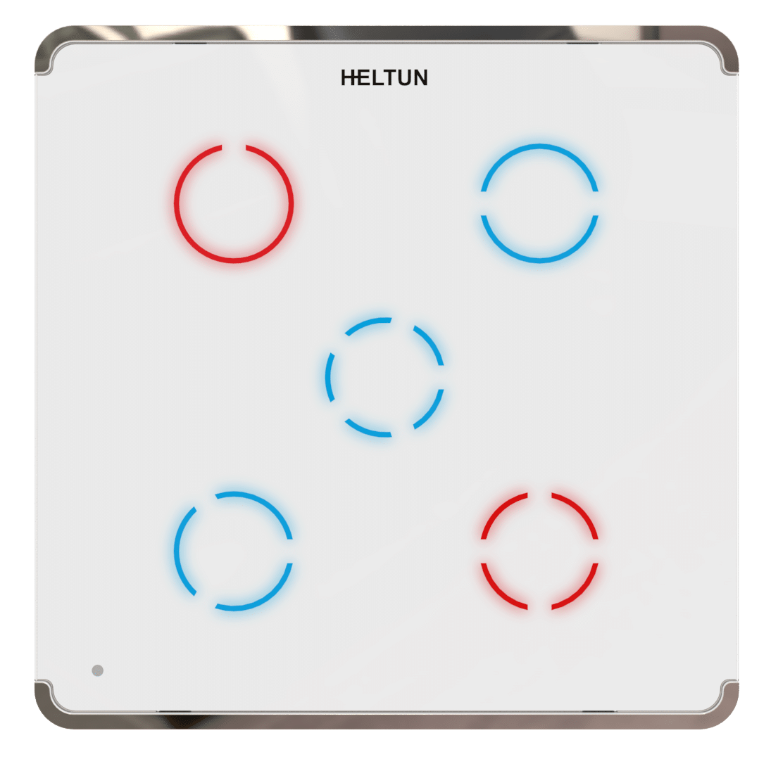
0 | 0 | Controlled by gateway or associated device | 1 | 1 | Controlled by touch button N1 (Top Left) | 2 | 2 | Controlled by touch button N2 (Top Right) | 3 | 3 | Controlled by touch button N3 (Bottom Left) | 4 | 4 | Controlled by touch button N4 (Bottom Right) | 5 | 5 | Controlled by touch button N5 (Center) |
|
24 | RELAY5 CONTROL SOURCE | Relay 5 control source | 2 | 1 | 0 | 5 | 5 | From | To | Description |
|---|
0 | 0 | Controlled by gateway or associated device | 1 | 1 | Controlled by touch button N1 (Top Left) | 2 | 2 | Controlled by touch button N2 (Top Right) | 3 | 3 | Controlled by touch button N3 (Bottom Left) | 4 | 4 | Controlled by touch button N4 (Bottom Right) | 5 | 5 | Controlled by touch button N5 (Center) |
|
25 | HOLD1 CONTROL MODE | Hold control mode for touch button 1 | 2 | 1 | 0 | 3 | 1 | From | To | Description |
|---|
0 | 0 | Hold function is disabled | 1 | 1 | Operate like click | 2 | 2 | When the button is held the relay output state is ON, as soon as the button is released the relay output state changes to OFF (momentary switch). | 3 | 3 | When the button is held the relay output state is OFF, as soon as the button is released the relay output state changes to ON (momentary switch). |
|
1 | TIME CORRECTION | Time correction by controller | 3 | 1 | 0 | 1 | 1 | From | To | Description |
|---|
0 | 0 | Switch off auto-correction | 1 | 0 | If TPS05 is connected to a Z-Wave gateway, the time and day will be periodically polled and corrected from the gateway |
|
2 | WEEKDAY | The day of the week (starting from Monday) | 3 | 1 | 1 | 7 | 1 | From | To | Description |
|---|
1 | 0 | Monday | 2 | 0 | Tuesday | 3 | 0 | Wednesday | 4 | 0 | Thursday | 5 | 0 | Friday | 6 | 0 | Saturday | 7 | 0 | Sunday |
|
3 | HOUR | Time Hour | 2 | 1 | 0 | 23 | 0 | From | To | Description |
|---|
0 | 23 | Time Hour in 24 hour format |
|
4 | MINUTE | Time Minute | 2 | 1 | 0 | 59 | 0 | From | To | Description |
|---|
0 | 59 | Manual adjustment of time minutes (60 minutes) |
|
7 | TEMPERATURE REPORT THRESHOLD | Temperature difference to send to controller, value X 10 | 2 | 1 | 0 | 100 | 5 | From | To | Description |
|---|
0 | 0 | Stop sending the reports | 1 | 100 | Temperature report threshhold (in °C) |
|
8 | HUMIDITY REPORT THRESHOLD | Humidity difference to send to controller, value X 10 | 2 | 1 | 0 | 25 | 2 | From | To | Description |
|---|
0 | 0 | Stop sending the reports | 1 | 25 | Humidity difference to send to controller, value X 10 |
|
9 | LIGHT REPORT THRESHOLD | Luminance difference to send to controller in % | 2 | 1 | 0 | 90 | 50 | From | To | Description |
|---|
0 | 0 | Stop sending the reports | 10 | 90 | The percentage (%) change in ambient illumination that results in a light sensor report being sent to the gateway |
|
11 | TEMP SENSOR CORRECTION | Temperature sensor calibration, x10 | 1 | 1 | -100 | 100 | 0 | From | To | Description |
|---|
-100 | 100 | Air temperature offset value (°C x 10) |
|
31 | CLICK2 CONTROL MODE | Click control mode for touch button 2 | 2 | 1 | 0 | 6 | 1 | From | To | Description |
|---|
0 | 0 | Click function disabled | 1 | 1 | Relay inverts state (toggles ON to OFF, OFF to ON). | 2 | 2 | Relay inverts state (toggles ON to OFF, OFF to ON) according to the button backlight state. | 3 | 3 | Relay switches to ON state only. | 4 | 4 | Relay switches to OFF state only. | 5 | 5 | Timer: On>Off Mode: Relay output switches to ON state (contacts are closed) then after a specified time switches back to OFF state (contacts are open). The time is specified in parameters 35-39. | 6 | 6 | Timer: OFF>ON Mode: Relay output switches to OFF state (contacts are open) then after a specified time switches back to ON state (contacts are closed). The time is specified in Parameters 35-39. |
|
5 | METER REPORT INTERVAL | Energy Consumption Meter Consecutive Report Interval, minutes | 2 | 1 | 1 | 120 | 10 | From | To | Description |
|---|
1 | 120 | Energy Consumption Meter Consecutive Report Interval in Minutes |
|
6 | SENSORS REPORT INTERVAL | Sensors Consecutive Report Interval | 2 | 1 | 1 | 120 | 10 | From | To | Description |
|---|
1 | 120 | Sensors Consecutive Report Interval in Minutes |
|
42 | RELAY CONTROL SCENARIO1 | Relays control by sensors Group 1 0, 10000000 … 53112359 Encoded as 8 digit value (ABCDEFGH): A: Relay number (1.. 5) B: Control Mode (0-Temperature Sensor, 1-Humidity Sensor, 2-Light Sensor, 3-Time control) C: State change condition relative to the value in HGFE Value field ( 0-Lower than, 1-Higher than) D: State Change, 0- Switch OFF, 1- Switch ON EFGH: Condition Value Sensor Value for Control modes 0-2 Time Of Day for Control mode 3. EF represents Hour (0..23), GH represents Minutes (0..59) | 2 | 4 | 0 | 53112359 | 0 | From | To | Description |
|---|
0 | 0 | Scenario function is disabled | 1 | 53112359 | Behavior according to the encoded scenario |
|
43 | RELAY CONTROL SCENARIO2 | Relays control by sensors Group 2 0, 10000000 … 53112359 Encoded as 8 digit value (ABCDEFGH): A: Relay number (1.. 5) B: Control Mode (0-Temperature Sensor, 1-Humidity Sensor, 2-Light Sensor, 3-Time control) C: State change condition relative to the value in HGFE Value field ( 0-Lower than, 1-Higher than) D: State Change, 0- Switch OFF, 1- Switch ON EFGH: Condition Value Sensor Value for Control modes 0-2 Time Of Day for Control mode 3. EF represents Hour (0..23), GH represents Minutes (0..59) | 2 | 4 | 0 | 53112359 | 0 | From | To | Description |
|---|
0 | 0 | Scenario function is disabled | 1 | 53112359 | Behavior according to the encoded scenario |
|
44 | RELAY CONTROL SCENARIO3 | Relays control by sensors Group 3 0, 10000000 … 53112359 Encoded as 8 digit value (ABCDEFGH): A: Relay number (1.. 5) B: Control Mode (0-Temperature Sensor, 1-Humidity Sensor, 2-Light Sensor, 3-Time control) C: State change condition relative to the value in HGFE Value field ( 0-Lower than, 1-Higher than) D: State Change, 0- Switch OFF, 1- Switch ON EFGH: Condition Value Sensor Value for Control modes 0-2 Time Of Day for Control mode 3. EF represents Hour (0..23), GH represents Minutes (0..59) | 2 | 4 | 0 | 53112359 | 0 | From | To | Description |
|---|
0 | 0 | Scenario function is disabled | 1 | 53112359 | Behavior according to the encoded scenario |
|
45 | RELAY CONTROL SCENARIO4 | Relays control by sensors Group 4 0, 10000000 … 53112359 Encoded as 8 digit value (ABCDEFGH): A: Relay number (1.. 5) B: Control Mode (0-Temperature Sensor, 1-Humidity Sensor, 2-Light Sensor, 3-Time control) C: State change condition relative to the value in HGFE Value field ( 0-Lower than, 1-Higher than) D: State Change, 0- Switch OFF, 1- Switch ON EFGH: Condition Value Sensor Value for Control modes 0-2 Time Of Day for Control mode 3. EF represents Hour (0..23), GH represents Minutes (0..59) | 2 | 4 | 0 | 53112359 | 0 | From | To | Description |
|---|
0 | 0 | Scenario function is disabled | 1 | 53112359 | Behavior according to the encoded scenario |
|
46 | RELAY CONTROL SCENARIO5 | Relays control by sensors Group 5 0, 10000000 … 53112359 Encoded as 8 digit value (ABCDEFGH): A: Relay number (1.. 5) B: Control Mode (0-Temperature Sensor, 1-Humidity Sensor, 2-Light Sensor, 3-Time control) C: State change condition relative to the value in HGFE Value field ( 0-Lower than, 1-Higher than) D: State Change, 0- Switch OFF, 1- Switch ON EFGH: Condition Value Sensor Value for Control modes 0-2 Time Of Day for Control mode 3. EF represents Hour (0..23), GH represents Minutes (0..59) | 2 | 4 | 0 | 53112359 | 0 | From | To | Description |
|---|
0 | 0 | Scenario function is disabled | 1 | 53112359 | Behavior according to the encoded scenario |
|
48 | RELAY CONTROL SCENARIO7 | Relays control by sensors Group 7. 0, 10000000 … 53112359 Encoded as 8 digit value (ABCDEFGH): A: Relay number (1.. 5) B: Control Mode (0-Temperature Sensor, 1-Humidity Sensor, 2-Light Sensor, 3-Time control) C: State change condition relative to the value in HGFE Value field ( 0-Lower than, 1-Higher than) D: State Change, 0- Switch OFF, 1- Switch ON EFGH: Condition Value Sensor Value for Control modes 0-2 Time Of Day for Control mode 3. EF represents Hour (0..23), GH represents Minutes (0..59) | 2 | 4 | 0 | 53112359 | 0 | From | To | Description |
|---|
0 | 0 | Scenario function is disabled | 1 | 53112359 | Behavior according to the encoded scenario |
|
47 | RELAY CONTROL SCENARIO6 | Relays control by sensors Group 6 0, 10000000 … 53112359 Encoded as 8 digit value (ABCDEFGH): A: Relay number (1.. 5) B: Control Mode (0-Temperature Sensor, 1-Humidity Sensor, 2-Light Sensor, 3-Time control) C: State change condition relative to the value in HGFE Value field ( 0-Lower than, 1-Higher than) D: State Change, 0- Switch OFF, 1- Switch ON EFGH: Condition Value Sensor Value for Control modes 0-2 Time Of Day for Control mode 3. EF represents Hour (0..23), GH represents Minutes (0..59) | 2 | 4 | 0 | 53112359 | 0 | From | To | Description |
|---|
0 | 0 | Scenario function is disabled | 1 | 53112359 | Behavior according to the encoded scenario |
|
49 | RELAY CONTROL SCENARIO8 | Relays control by sensors Group 8 0, 10000000 … 53112359 Encoded as 8 digit value (ABCDEFGH): A: Relay number (1.. 5) B: Control Mode (0-Temperature Sensor, 1-Humidity Sensor, 2-Light Sensor, 3-Time control) C: State change condition relative to the value in HGFE Value field ( 0-Lower than, 1-Higher than) D: State Change, 0- Switch OFF, 1- Switch ON EFGH: Condition Value Sensor Value for Control modes 0-2 Time Of Day for Control mode 3. EF represents Hour (0..23), GH represents Minutes (0..59) | 2 | 4 | 0 | 53112359 | 0 | From | To | Description |
|---|
0 | 0 | Scenario function is disabled | 1 | 53112359 | Behavior according to the encoded scenario |
|
50 | RELAY CONTROL SCENARIO9 | Relays control by sensors Group 9 0, 10000000 … 53112359 Encoded as 8 digit value (ABCDEFGH): A: Relay number (1.. 5) B: Control Mode (0-Temperature Sensor, 1-Humidity Sensor, 2-Light Sensor, 3-Time control) C: State change condition relative to the value in HGFE Value field ( 0-Lower than, 1-Higher than) D: State Change, 0- Switch OFF, 1- Switch ON EFGH: Condition Value Sensor Value for Control modes 0-2 Time Of Day for Control mode 3. EF represents Hour (0..23), GH represents Minutes (0..59) | 2 | 4 | 0 | 53112359 | 0 | From | To | Description |
|---|
0 | 0 | Scenario function is disabled | 1 | 53112359 | Behavior according to the encoded scenario |
|
51 | RELAY CONTROL SCENARIO10 | Relays control by sensors Group 10 0, 10000000 … 53112359 Encoded as 8 digit value (ABCDEFGH): A: Relay number (1.. 5) B: Control Mode (0-Temperature Sensor, 1-Humidity Sensor, 2-Light Sensor, 3-Time control) C: State change condition relative to the value in HGFE Value field ( 0-Lower than, 1-Higher than) D: State Change, 0- Switch OFF, 1- Switch ON EFGH: Condition Value Sensor Value for Control modes 0-2 Time Of Day for Control mode 3. EF represents Hour (0..23), GH represents Minutes (0..59) | 2 | 4 | 0 | 53112359 | 0 | From | To | Description |
|---|
1 | 53112359 | Behavior according to the encoded scenario | 0 | 0 | Scenario function is disabled |
|
52 | RELAY1 LOAD POWER | Power load consumption (in Watts) Relay channel 1 in order to calculate total energy consumption relative to the time each relay is ON. | 2 | 2 | 0 | 1100 | 0 | From | To | Description |
|---|
0 | 1100 | Power load consumption (in Watts) |
|
53 | RELAY2 LOAD POWER | Power load consumption (in Watts) Relay channel 2 in order to calculate total energy consumption relative to the time each relay is ON. | 2 | 2 | 0 | 1100 | 0 | From | To | Description |
|---|
0 | 1100 | Power load consumption (in Watts) |
|
54 | RELAY3 LOAD POWER | Power load consumption (in Watts) Relay channel 3 in order to calculate total energy consumption relative to the time each relay is ON. | 2 | 2 | 0 | 1100 | 0 | From | To | Description |
|---|
0 | 1100 | Power load consumption (in Watts) |
|
55 | RELAY4 LOAD POWER | Power load consumption (in Watts) Relay channel 4 in order to calculate total energy consumption relative to the time each relay is ON. | 2 | 2 | 0 | 1100 | 0 | From | To | Description |
|---|
0 | 1100 | Power load consumption (in Watts) |
|
56 | RELAY5 LOAD POWER | Power load consumption (in Watts) Relay channel 5 in order to calculate total energy consumption relative to the time each relay is ON. | 2 | 2 | 0 | 1100 | 0 | From | To | Description |
|---|
0 | 1100 | Power load consumption (in Watts) |
|
57 | TOUCH1 ASSOCIATION MODE | Touch control mode for associations with touch button 1. This parameter is intended for use when Multilevel Switch Group Associations (Groups 3, 5, 7, 9, & 11) have been activated. Defines the logic of values changing if one the touch button has been held for more than one second. | 3 | 1 | 0 | 2 | 0 | From | To | Description |
|---|
0 | 0 | On each hold event, “UP (brighten)” and “DOWN (dim)” command will be alternately sent to associated devices. | 1 | 0 | On each hold event, the “UP (brighten)” command will be sent to associated devices. | 2 | 0 | On each hold event, the “DOWN (dim)” command will be sent to associated devices. |
|
58 | TOUCH2 ASSOCIATION MODE | Touch control mode for associations with touch button 2. This parameter is intended for use when Multilevel Switch Group Associations (Groups 3, 5, 7, 9, & 11) have been activated. Defines the logic of values changing if one the touch button has been held for more than one second. | 3 | 1 | 0 | 2 | 0 | From | To | Description |
|---|
0 | 0 | On each hold event, “UP (brighten)” and “DOWN (dim)” command will be alternately sent to associated devices. | 1 | 0 | On each hold event, the “UP (brighten)” command will be sent to associated devices. | 2 | 0 | On each hold event, the “DOWN (dim)” command will be sent to associated devices. |
|
59 | TOUCH3 ASSOCIATION MODE | Touch control mode for associations with touch button 3. This parameter is intended for use when Multilevel Switch Group Associations (Groups 3, 5, 7, 9, & 11) have been activated. Defines the logic of values changing if one the touch button has been held for more than one second. | 3 | 1 | 0 | 2 | 0 | From | To | Description |
|---|
0 | 0 | On each hold event, “UP (brighten)” and “DOWN (dim)” command will be alternately sent to associated devices. | 1 | 0 | On each hold event, the “UP (brighten)” command will be sent to associated devices. | 2 | 0 | On each hold event, the “DOWN (dim)” command will be sent to associated devices. |
|
60 | TOUCH4 ASSOCIATION MODE | Touch control mode for associations with touch button 4. This parameter is intended for use when Multilevel Switch Group Associations (Groups 3, 5, 7, 9, & 11) have been activated. Defines the logic of values changing if one the touch button has been held for more than one second. | 3 | 1 | 0 | 2 | 0 | From | To | Description |
|---|
0 | 0 | On each hold event, “UP (brighten)” and “DOWN (dim)” command will be alternately sent to associated devices. | 1 | 0 | On each hold event, the “UP (brighten)” command will be sent to associated devices. | 2 | 0 | On each hold event, the “DOWN (dim)” command will be sent to associated devices. |
|
61 | TOUCH5 ASSOCIATION MODE | Touch control mode for associations with touch button 5. This parameter is intended for use when Multilevel Switch Group Associations (Groups 3, 5, 7, 9, & 11) have been activated. Defines the logic of values changing if one the touch button has been held for more than one second. | 3 | 1 | 0 | 2 | 0 | From | To | Description |
|---|
0 | 0 | On each hold event, “UP (brighten)” and “DOWN (dim)” command will be alternately sent to associated devices. | 1 | 0 | On each hold event, the “UP (brighten)” command will be sent to associated devices. | 2 | 0 | On each hold event, the “DOWN (dim)” command will be sent to associated devices. |
|