| Product Recognition | |
|---|
| Certification Number | ZC10-14120001 |
|---|
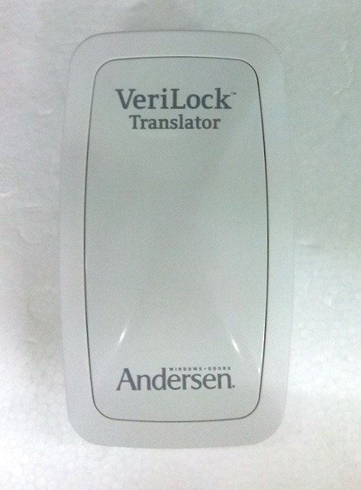
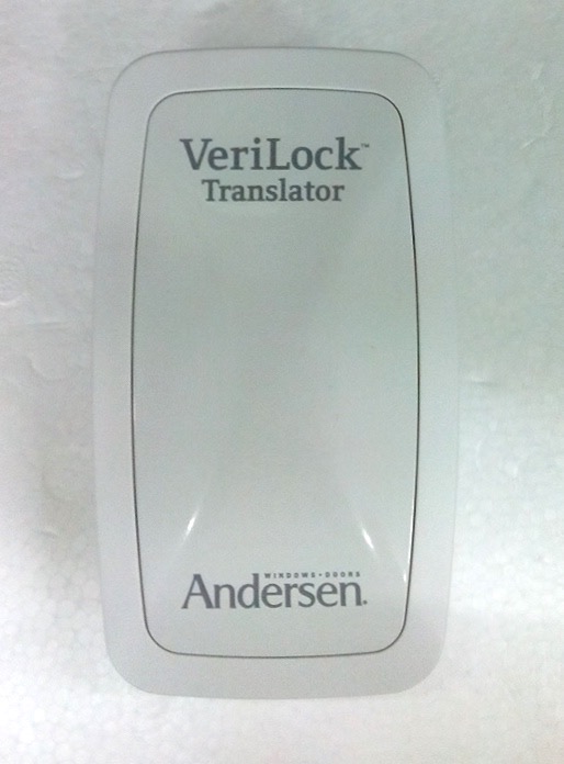
| Name | VeriLock Translator |
|---|
| Short Description | The VeriLock Translator™ is a Z-Wave Plus Repeater that receives messages from VeriLock™ Sensors and reports their status over the Z-Wave network to a Z-Wave Controller. |
|---|
| Long Description | The VeriLock Translator™ is an indoor device that allows users to monitor the status of over 100 VeriLock™ sensors by Nexia Home Intelligence™ using standard Z-Wave interfaces.
These sensors are added to the VeriLock Translator™ as Multi Channel End Points. Because the number of sensors in a home is dynamic, the number of End Points on the device is also dynamic. Unlike the VeriLock Translator™, the sensors are NEVER represented as nodes on the Z-Wave network and cannot communicate over the Z-Wave network. Their status, however, is reported by the VeriLock Translator™ over the Z-Wave network via the Multi Channel Command Class.
The VeriLock Translator™ is added to the Z-Wave network as a Repeater and implements the Routing Slave library. The VeriLock Translator™ is a Z-Wave Plus certified device. |
|---|
| Brand | Andersen |
|---|
| Product Identifier | 9125051 |
|---|
| OEM Version | 1 |
|---|
| Hardware Platform | ZM5202 |
|---|
| Z-Wave Version | 6.51.03 |
|---|
| Library Type | SLAVE_ROUTING |
|---|
| Device Type | Repeater |
|---|
| Role Type | ROLE_TYPE_SLAVE_ALWAYS_ON |
|---|
| Manufacturer ID | 0x0178 |
|---|
| Product Type ID | 0x5A44 |
|---|
| Product ID | 0x414E |
|---|
| Frequency Plans | US: 916.00MHz, 908.40MHz |
|---|
| Categories | Sensors |
|---|
| Countries / Regions | United States of America |
|---|
| Documents | |
|---|
| Association Groups | | Group Number | Maximum Nodes Supported | End Point ID | Description |
|---|
| 1 | 1 | 0 | Z-Wave Plus Lifeline |
|
|---|
| Configuration Parameters | | Parameter Number | Name | Description | Format | Size | Min Value | Max Value | Default Value | Parameter Values |
|---|
| 2 | Discovery Mode | Start, stop, or get the results of Discovery Mode. Retrieve the configuration parameter to obtain the results of discovery mode: 0=Not Enabled, 1=Enabled, 2=Timed Out, 3=Failure | 0 | 1 | 0 | 0 | 0 | | From | To | Description |
|---|
| 0 | 0 | Disable | | 1 | 1 | Enable |
| | 3 | Sleep Mode | Turn Sleep Mode ON or OFF. | 0 | 1 | 0 | 0 | 0 | | From | To | Description |
|---|
| 0 | 0 | OFF | | 1 | 1 | ON |
| | 1 | Buzzer Volume | Adjust the buzzer volume | 0 | 1 | 0 | 0 | 100 | | From | To | Description |
|---|
| 0 | 100 | 100 is max volume. 0 is off. |
|
|
|---|
| Texts | | ID | Description | Value |
|---|
| 1 | Inclusion | If not included to a Z-Wave network, the device will attempt to be added to the network at power-up following an LED start-up sequence. The controller must be put into include mode before plugging in the device.
During normal operation, after putting the controller into include mode, a single press of the round Z-Wave button will add the device to the Z-Wave network. | | 2 | Exclusion | After putting the controller in exclude mode, a single press of the round Z-Wave button will remove the device from the Z-Wave network. | | 5 | Factory Reset | The device is factory reset by pressing and holding both the round (Z-Wave) and square (Multi-Purpose) buttons simultaneously for 15 seconds. Please use this procedure only in emergencies such as when the network primary controller is missing or otherwise inoperable. This should always be used as a last resort. |
|
|---|
| Supports NWI | Yes |
|---|
| Supports Explorer Frames | Yes |
|---|


