Product Recognition | |
|---|
Certification Number | ZC14-24010389 |
|---|
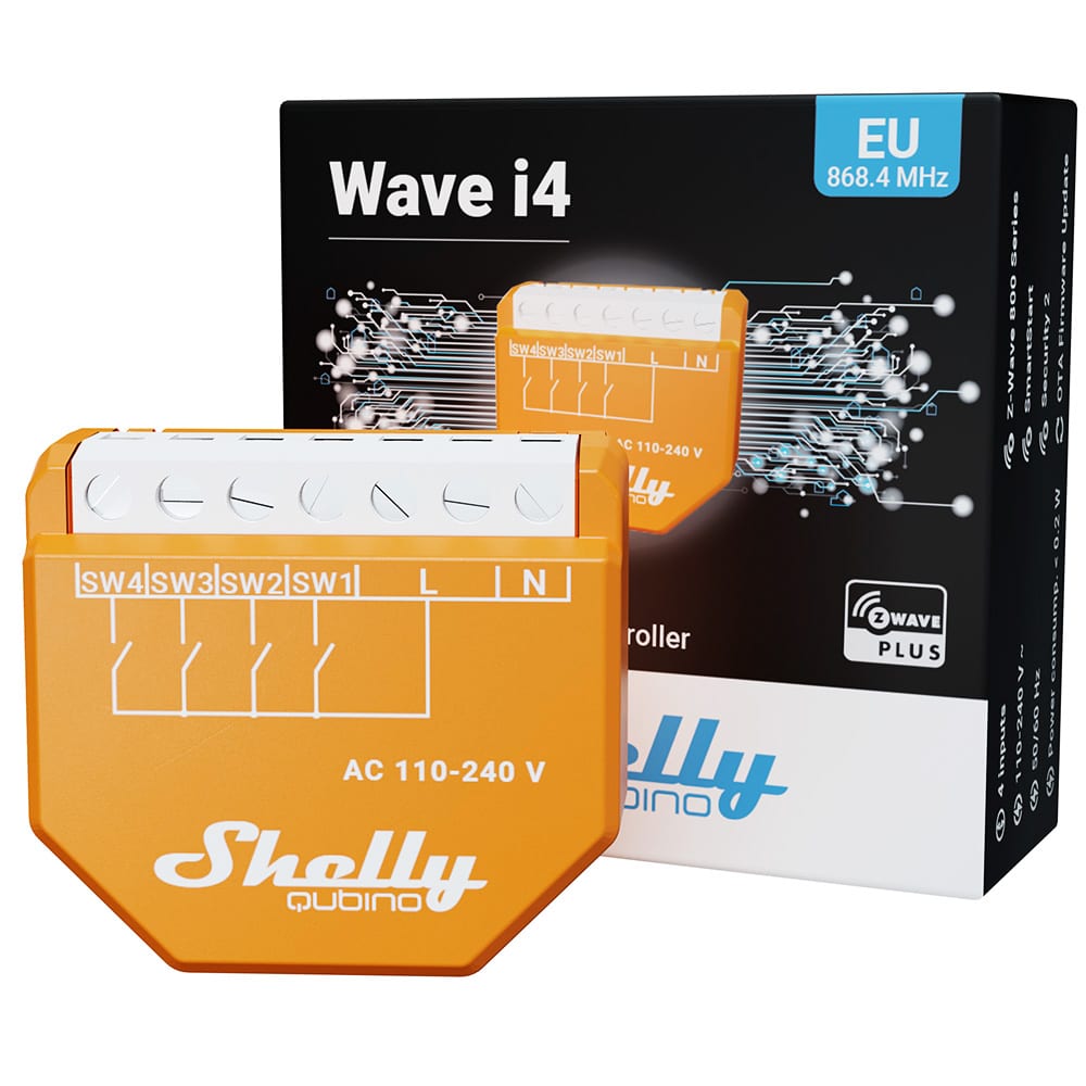
Name | Wave i4 |
|---|
Short Description | Wave i4 is a 4-digital inputs controller with which you can manually activate or deactivate any created scene, run synchronized actions, or execute complex trigger scenarios. |
|---|
Long Description | Z-Wave® 4-digital inputs controller for enhanced actions control
Manually activate or deactivate any created scene, run synchronized actions, or execute complex trigger scenarios.
Wave i4 is an input reader device (it does not contain relays).
Manually control other Z-Wave devices (e.g. with a multi-button switch)
Multi-click – activation of up to 12 actions
Extremely low power consumption: < 0.2 W
Z-Wave frequency band: 868.4 MHz (CEPT countries)
Latest technology: Z-Wave 800 Series
Automatic set-up with SmartStart
Security 2 Authenticated for the highest level of security
Over-the-air firmware updates
Works with Z-Wave-certified gateways and over 4,000 Z-Wave devices |
|---|
Brand | Shelly Qubino |
|---|
Product Identifier | QNSN-0A24XEU |
|---|
Product Line | Wave |
|---|
OEM Version | HW: 01 FW: 11.01:02.02 |
|---|
Hardware Platform | ZGM230SA |
|---|
Z-Wave Version | 7.19.1 |
|---|
Library Type | END_NODE_ENHANCED_232 |
|---|
Device Type | Central Scene DT |
|---|
Role Type | ROLE_TYPE_END_NODE_ALWAYS_ON |
|---|
Manufacturer ID | 0x0460 |
|---|
Product Type ID | 0x0009 |
|---|
Product ID | 0x0081 |
|---|
User Icon | 0x1D04 |
|---|
Installer Icon | 0x1D04 |
|---|
Frequency Plans | EU: 869.85MHz, 868.40MHz |
|---|
Categories | All Controllers |
|---|
Countries / Regions | Armenia, Bahrain, European Union, Cyprus, Moldova, Egypt, French Guiana, Georgia, Iraq, Jordan, Kazakhstan, Kuwait, Lebanon, Libya, Maldives, Mauritius, Nigeria, Oman, Philippines, Qatar, Saudi Arabia, South Africa, Turkmenistan, United Arab Emirates, ZU, Yemen |
|---|
Supported Command Classes | Identifier | Name | Key | Version |
|---|
COMMAND_CLASS_CENTRAL_SCENE_V3 | Central Scene V3 | 0x5B | 3 | COMMAND_CLASS_CONFIGURATION_V4 | Configuration V4 | 0x70 | 4 | COMMAND_CLASS_NOTIFICATION_V8 | Notification V8 | 0x71 | 8 | COMMAND_CLASS_ASSOCIATION_V2 | Association V2 | 0x85 | 2 | COMMAND_CLASS_ASSOCIATION_GRP_INFO_V3 | Association Group Information (AGI) V3 | 0x59 | 3 | COMMAND_CLASS_DEVICE_RESET_LOCALLY | Device Reset Locally | 0x5A | 1 | COMMAND_CLASS_FIRMWARE_UPDATE_MD_V5 | Firmware Update Meta Data V5 | 0x7A | 5 | COMMAND_CLASS_INDICATOR_V3 | Indicator V3 | 0x87 | 3 | COMMAND_CLASS_MANUFACTURER_SPECIFIC_V2 | Manufacturer Specific V2 | 0x72 | 2 | COMMAND_CLASS_MULTI_CHANNEL_ASSOCIATION_V3 | Multi Channel Association V3 | 0x8E | 3 | COMMAND_CLASS_VERSION_V3 | Version V3 | 0x86 | 3 | COMMAND_CLASS_ZWAVEPLUS_INFO_V2 | Z-Wave Plus Info V2 | 0x5E | 2 | COMMAND_CLASS_SECURITY | Security 0 | 0x98 | 1 | COMMAND_CLASS_SECURITY_2 | Security 2 | 0x9F | 1 | COMMAND_CLASS_SUPERVISION | Supervision | 0x6C | 1 | COMMAND_CLASS_TRANSPORT_SERVICE_V2 | Transport Service V2 | 0x55 | 2 | COMMAND_CLASS_POWERLEVEL | Powerlevel | 0x73 | 1 |
|
|---|
S2 Classes | S2_AUTHENTICATED, S2_UNAUTHENTICATED |
|---|
Documents | Category | File |
|---|
Manual_English | | Adv_Manual | |
|
|---|
Features | Feature | Values |
|---|
Color | | Firmware Updatable | Value |
|---|
Updatable by Consumer by RF |
| Neutral Wire Required | | Switch Type | |
|
|---|
Association Groups | Group Number | Maximum Nodes Supported | End Point ID | Group Name | Profile |
|---|
1 | 9 | 0 | Lifeline | 0x0001 | 2 | 9 | 0 | On/Off [SW1] | 0x2001 | 3 | 9 | 0 | Start/Stop [SW1] | 0x2001 | 4 | 9 | 0 | On/Off [SW2] | 0x2002 | 5 | 9 | 0 | Start/Stop [SW2] | 0x2002 | 6 | 9 | 0 | On/Off [SW3] | 0x2003 | 7 | 9 | 0 | Start/Stop [SW3] | 0x2003 | 8 | 9 | 0 | On/Off [SW4] | 0x2004 | 9 | 9 | 0 | Start/Stop [SW4] | 0x2004 |
|
|---|
Configuration Parameters | Parameter Number | Name | Description | Format | Size | Min Value | Max Value | Default Value | Flag Advanced | Read-only |
|---|
1 | SW1 Switch type | 0 push, 1 toggle state, 2 toggle change | 1 | 1 | 0 | 0 | 0x00 | | | 2 | SW2 Switch type | 0 push, 1 toggle state, 2 toggle change | 1 | 1 | 0 | 0 | 0x00 | | | 3 | SW3 Switch type | 0 push, 1 toggle state, 2 toggle change | 1 | 1 | 0 | 0 | 0x00 | | | 4 | SW4 Switch type | 0 push, 1 toggle state, 2 toggle change | 1 | 1 | 0 | 0 | 0x00 | | | 105 | LED Intensity | Control LEd intensity, 0 - 100 | 1 | 1 | 0 | 0 | 0x64 | | | 120 | Factory reset | Factory reset | 1 | 1 | 0 | 0 | 0x00 | Yes | | 201 | Serial Number 1 | Serial Number 1 | 1 | 4 | 0 | 0 | 0x7FFFFFFF | Yes | Yes | 202 | Serial Number 2 | Serial Number 2 | 1 | 4 | 0 | 0 | 0x7FFFFFFF | Yes | Yes | 203 | Serial Number 3 | Serial Number 3 | 1 | 4 | 0 | 0 | 0x7FFFFFFF | Yes | Yes |
|
|---|
Texts | ID | Description | Value |
|---|
8 | Where to find S2 DSK on product | When adding the Device to a Z-Wave network with a gateway supporting Security 2 (S2), the PIN Code of the Z-Wave Device Specific Key (DSK) is required. You can find it on the label on the side of the Device and a copy is inserted in the packaging, which must not be lost. Do not remove the Z-Wave DSK label from the Device. As a backup measure, use the label in the packaging. The first five digits of the key are highlighted or underlined to help the user identify the PIN Code part of the DSK text. The DSK is additionally represented with a QR Code as shown on the image. | 1 | Classic Inclusion | 6.1 Adding the Device to a Z-Wave® network (inclusion)
Note! In case of Security 2 (S2) adding (inclusion), a dialog will appear asking you to enter the corresponding PIN Code (5 underlined digits) that are written on the Z-Wave® DSK label on the side of the Device and on the Z-Wave® DSK label inserted in the packaging.
IMPORTANT: The PIN Code must not be lost.
6.1.1. SmartStart adding (inclusion)
SmartStart enabled products can be added into a Z-Wave® network by scanning the Z-Wave® QR Code present on the Device with a gateway providing SmartStart inclusion. No further action is required, and the SmartStart device will be added automatically within 10 minutes of being switched on in the network vicinity.
1. With the gateway application scan the QR code on the Device label and add the Security 2 (S2) Device Specific Key (DSK) to the provisioning list in the gateway.
2. Connect the Device to a power supply.
3. Check if the blue LED is blinking in Mode 1. If so, the Device is not added to a Z-Wave® network.
4. Adding will be initiated automatically within a few seconds after connecting the Device to a power supply, and the Device will be added to a Z-Wave® network automatically.
5. The blue LED will be blinking in Mode 2 during the adding process.
6. The green LED will be blinking in Mode 1 if the Device is successfully added to a Z-Wave® network.
6.1.2. Adding (inclusion) with the S button
1. Connect the Device to a power supply.
2. Check if the blue LED is blinking in Mode 1. If so, the Device is not added to a Z-Wave® network.
3. Enable add/remove mode on the gateway.
4. To enter the Setting mode, quickly press and hold the S button on the Device until the LED turns solid blue.
5. Quickly release and then press and hold (> 2s) the S button on the Device until the blue LED starts blinking in Mode 3. Releasing the S button will start the Learn mode.
6. The blue LED will be blinking in Mode 2 during the adding process.
7. The green LED will be blinking in Mode 1 if the Device is successfully added to a Z-Wave® network.
Note! In Setting mode, the Device has a timeout of 10s before entering again into Normal mode.
6.1.3. Adding (inclusion) with a switch/push-button
1. Connect the Device to a power supply.
2. Check if the blue LED is blinking in Mode 1. If so, the Device is not added to a Z-Wave® network.
3. Enable add/remove mode on the gateway.
4. Toggle the switch/push-button connected to any of the SW terminals (SW, SW1, SW2, etc.) 3 times within 3 seconds (this procedure puts the Device in Learn mode*). The Device must receive on/off signal 3 times, which means pressing the momentary switch 3 times, or toggling the switch on and off 3 times.
5. The blue LED will be blinking in Mode 2 during the adding process.
6. The green LED will be blinking in Mode 1 if the Device is successfully added to a Z-Wave® network.
*Learn mode - a state that allows the Device to receive network information from the gateway. | 2 | Classic Exclusion | 6.2 Removing the Device from a Z-Wave® network (exclusion)
Note! The Device will be removed from your Z-Wave® network, but any custom configuration parameters will not be erased.
6.2.1. Removing (exclusion) with the S button
1. Connect the Device to a power supply.
2. Check if the green LED is blinking in Mode 1. If so, the Device is added to a Z-Wave® network.
3. Enable add/remove mode on the gateway.
4. To enter the Setting mode, quickly press and hold the S button on the Device until the LED turns solid blue.
5. Quickly release and then press and hold (> 2s) the S button on the Device until the blue LED starts blinking in Mode 3. Releasing the S button will start the Learn mode.
6. The blue LED will be blinking in Mode 2 during the removing process.
7. The blue LED will be blinking in Mode 1 if the Device is successfully removed from a Z-Wave® network.
Note! In Setting mode, the Device has a timeout of 10s before entering again into Normal mode.
6.2.2. Removing (exclusion) with switch/push-button
1. Connect the Device to a power supply.
2. Check if the green LED is blinking in Mode 1. If so, the Device is added to a Z-Wave® network.
3. Enable add/remove mode on the gateway.
4. Toggle the switch/push-button connected to any of the SW terminals (SW, SW1, SW2,…) 3 times within 3 seconds (this procedure puts the Device in Learn mode). The Device must receive on/off signal 3 times, which means pressing the momentary switch 3 times, or toggling the switch on and off 3 times.
5. The blue LED will be blinking in Mode 2 during the removing process.
6. The blue LED will be blinking in Mode 1 if the Device is successfully removed from a Z-Wave® network. | 5 | Factory Reset Procedure | 6.3 Factory reset
6.3.1 Factory reset general
After Factory reset, all custom parameters and stored values (kWh, associations, routings, etc.) will return to their default state. HOME ID and NODE ID assigned to the Device will be deleted. Use this reset procedure only when the gateway is missing or otherwise inoperable.
6.3.2 Factory reset with the S button
Note! Factory reset with the S button is possible anytime.
1. To enter the Setting mode, quickly press and hold the S button on the Device until the LED turns solid blue.
2. Press the S button multiple times until the LED turns solid red.
3. Press and hold (> 2s) S button on the Device until the red LED starts blinking in Mode 3. Releasing the S button will start the factory reset.
4. During factory reset, the LED will turn solid green for about 1s, then the blue and red LED will start blinking in Mode 3 for approx. 2s.
5. The blue LED will be blinking in Mode 1 if the Factory reset is successful.
6.3.3 Factory reset with a switch/push-button
Note! Factory reset with a switch/push-button is only possible within the first minute after the Device is connected to a power supply.
1. Connect the Device to a power supply.
2. Toggle the switch/push-button connected to any of the SW terminals (SW, SW1, SW2,…) 5 times within 3 seconds. The Device must receive on/off signal 5 times, which means pressing the push-button 5 times, or toggling the switch on and off 5 times.
3. During factory reset, the LED will turn solid green for about 1s, then the blue and red LED will start blinking in Mode 3 for approx. 2s.
4. The blue LED will be blinking in Mode 1 if the Factory reset is successful. |
|
|---|
Supported Notification Types | Notification Type | Event / State |
|---|
Heat Alarm | Heat sensor status: Overheat detected |
|
|---|
Supports NWI | Yes |
|---|
Supports Explorer Frames | Yes |
|---|
Supports SmartStart | Yes |
|---|
Radio Range Z-Wave (m) | 40 |
|---|