Product Recognition | |
|---|
Certification Number | ZC10-17025415 |
|---|
Name | WT00Z5-1 |
|---|
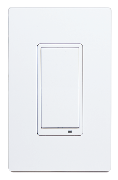
Short Description | An in-wall wireless 3-way lighting dimmer switch. Controls Associated devices and, with Central Scene support, can run up to 6 scenes created by the Hub. Over The Air upgradable. |
|---|
Long Description | The WT00Z5-1 is an in-wall wireless 3-way lighting dimmer switch. Not only can this switch control Associated devices, with Central Scene support it can run up to 6 scenes created by the Hub it is the most versatile Home Automation light switch available. With OTA upgrading supported, this light switch may be the last one ever installed in a home. |
|---|
Brand | GoControl |
|---|
Product Identifier | WT00Z5-1 |
|---|
OEM Version | HW: 1 FW: 1.22 |
|---|
Hardware Platform | ZM5202 |
|---|
Z-Wave Version | 6.51.09 |
|---|
Library Type | SLAVE_ENHANCED_232 |
|---|
Device Type | Wall Controller |
|---|
Role Type | ROLE_TYPE_SLAVE_ALWAYS_ON |
|---|
Manufacturer ID | 0x014F |
|---|
Product Type ID | 0x5754 |
|---|
Product ID | 0x3530 |
|---|
User Icon | 0x1600 |
|---|
Installer Icon | 0x1600 |
|---|
Frequency Plans | US: 916.00MHz, 908.40MHz |
|---|
Categories | All Lighting Devices, Dimming Lighting Devices |
|---|
Countries / Regions | United States of America |
|---|
Supported Command Classes | Identifier | Name | Key | Version |
|---|
COMMAND_CLASS_POWERLEVEL | Powerlevel | 0x73 | 1 | COMMAND_CLASS_VERSION_V2 | Version V2 | 0x86 | 2 | COMMAND_CLASS_DEVICE_RESET_LOCALLY | Device Reset Locally | 0x5A | 1 | COMMAND_CLASS_ZWAVEPLUS_INFO_V2 | Z-Wave Plus Info V2 | 0x5E | 2 | COMMAND_CLASS_ASSOCIATION_V2 | Association V2 | 0x85 | 2 | COMMAND_CLASS_ASSOCIATION_GRP_INFO | Association Group Info | 0x59 | 1 | COMMAND_CLASS_BASIC_V2 | Basic V2 | 0x20 | 2 | COMMAND_CLASS_CONFIGURATION_V3 | Configuration V3 | 0x70 | 3 | COMMAND_CLASS_CENTRAL_SCENE_V2 | Central Scene V2 | 0x5B | 2 | COMMAND_CLASS_FIRMWARE_UPDATE_MD_V2 | Firmware Update Meta-Data V2 | 0x7A | 2 | COMMAND_CLASS_MANUFACTURER_SPECIFIC_V2 | Manufacturer Specific V2 | 0x72 | 2 |
|
|---|
Controlled Command Classes | Identifier | Name | Key | Version |
|---|
COMMAND_CLASS_SWITCH_MULTILEVEL | Switch Multilevel | 0x26 | 1 | COMMAND_CLASS_BASIC_V2 | Basic V2 | 0x20 | 2 |
|
|---|
Documents | Category | Description | File |
|---|
Manual_Primary_Lang | Product or Owner's Manual | |
|
|---|
Features | Feature | Values |
|---|
Color | | Firmware Updatable | Value |
|---|
Updatable by Consumer via Internet |
| Neutral Wire Required | | Z-Wave Scene Type | |
|
|---|
Association Groups | Group Number | Maximum Nodes Supported | End Point ID | Description |
|---|
1 | 5 | 0 | Z-Wave Plus Lifeline |
|
|---|
Configuration Parameters | Parameter Number | Name | Description | Format | Size | Min Value | Max Value | Default Value | Parameter Values |
|---|
3 | Night Light | The Night Light function can be configured to be OFF when the Associated device is turned ON (default), be made to have the LED turn ON when the Associated device is turned ON or be OFF at all times. | 0 | 1 | 0 | 0 | 0 | From | To | Description |
|---|
0 | 4 | 0 - LED OFF when the load is on, and ON when the load is off. 1 - LED ON when the load is on, and OFF when the load is off. 2 - LED is always on. 3 - LED is always off. 4 - LED blinks during RF transmissions from or to the device. |
| 4 | Invert Switch | Used to change the top of the switch to OFF and the bottom of the switch ON | 0 | 1 | 0 | 0 | 0 | From | To | Description |
|---|
0 | 1 | 0 - Top of switch is ON, bottom of switch is OFF. 1 - Bottom of switch is ON, top of switch is OFF |
|
|
|---|
Texts | ID | Description | Value |
|---|
5 | Factory Reset | To Reset Unit (If Required):
In the event that your primary Controller is lost or otherwise inoperable, to reset
the WT00Z5-1 and clear all network information, follow these steps:
1. Tap the top of the switch fi ve (5) times.
2. Press and hold the bottom of the switch for 15 seconds. The LED will
increasingly blink faster to indicate that a Reset is taking place. | 1 | Inclusion | Adding to a network:
Refer to your Controller operating instructions to add this switch under the
command of the Wireless Controller.
1. With your Controller in Discovery or Add Mode, tap the switch. The LED will
blink slowly when in ADD Mode.
2. You should see an indication on your Controller that the “device was added”
to the network and the LED will stop blinking.
3. The device will appear in the list of Switches. It should display as a switch.
If the Controller/Gateway shows the addition failed, repeat Steps 1-3. | 2 | Exclusion | Removing from a network:
The WT00Z5-1 can be removed from the network by the Controller/Gateway.
Refer to the Controller operating instructions for details.
1. Set the Controller into Removal Mode and follow its instruction to delete the
WT00Z5-1 from the Controller.
2. Remove the switch by tapping the paddle 2 times. The LED will begin
blinking slowly for 10 seconds indicating that it has been removed.
3. You should see an indication on your Controller that the “device was
removed” from the network. |
|
|---|
Supports NWI | Yes |
|---|
Supports Explorer Frames | Yes |
|---|
Radio Range Z-Wave (m) | 40 |
|---|