| Product Recognition | |
|---|
| Certification Number | ZC10-17065660 |
|---|
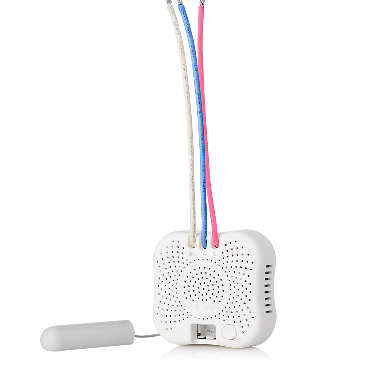
| Name | insert module swtich |
|---|
| Short Description | 2 Gang Insert Module Switch ,single live wire,light control |
|---|
| Long Description | 2 Gang Insert Module Switch is designed to operate without neutral wire. It operates with different loads, including Incandescent lamps, halogen lamps or LEDS. It can act as repeaters regardless of vendor to increase reliability of the network. |
|---|
| Brand | Kuju |
|---|
| Product Identifier | IMZ6220 |
|---|
| OEM Version | HW: 2 FW: 2.23 |
|---|
| Hardware Platform | ZM5202 |
|---|
| Z-Wave Version | 6.51.09 |
|---|
| Library Type | SLAVE_ROUTING |
|---|
| Device Type | On/Off Power Switch |
|---|
| Role Type | ROLE_TYPE_SLAVE_ALWAYS_ON |
|---|
| Manufacturer ID | 0x0111 |
|---|
| Product Type ID | 0x5001 |
|---|
| Product ID | 0x6260 |
|---|
| User Icon | 0x0700 |
|---|
| Installer Icon | 0x0700 |
|---|
| Frequency Plans | EU: 869.85MHz, 868.40MHz |
|---|
| Categories | All Lighting Devices, On/Off Switches/Devices, Lighting Accessories |
|---|
| Countries / Regions | European Union |
|---|
| Supported Command Classes | | Identifier | Name | Key | Version |
|---|
| COMMAND_CLASS_POWERLEVEL | Powerlevel | 0x73 | 1 | | COMMAND_CLASS_MULTI_CHANNEL_ASSOCIATION_V3 | Multi-Channel Association V3 | 0x8E | 3 | | COMMAND_CLASS_SWITCH_ALL | Switch All | 0x27 | 1 | | COMMAND_CLASS_SWITCH_BINARY | Switch Binary | 0x25 | 1 | | COMMAND_CLASS_BASIC | Basic | 0x20 | 1 | | COMMAND_CLASS_CONFIGURATION | Configuration | 0x70 | 1 | | COMMAND_CLASS_VERSION_V2 | Version V2 | 0x86 | 2 | | COMMAND_CLASS_DEVICE_RESET_LOCALLY | Device Reset Locally | 0x5A | 1 | | COMMAND_CLASS_ZWAVEPLUS_INFO_V2 | Z-Wave Plus Info V2 | 0x5E | 2 | | COMMAND_CLASS_ASSOCIATION_V2 | Association V2 | 0x85 | 2 | | COMMAND_CLASS_ASSOCIATION_GRP_INFO | Association Group Info | 0x59 | 1 | | COMMAND_CLASS_MULTI_CHANNEL_V4 | Multi-Channel V4 | 0x60 | 4 | | COMMAND_CLASS_MANUFACTURER_SPECIFIC_V2 | Manufacturer Specific V2 | 0x72 | 2 |
|
|---|
| Controlled Command Classes | | Identifier | Name | Key | Version |
|---|
| COMMAND_CLASS_BASIC | Basic | 0x20 | 1 |
|
|---|
| Documents | |
|---|
| Features | | Feature | Values |
|---|
| Loads Controlled | | | Neutral Wire Required | | | Color | | | Outdoor Use | | | Switch Type | | Value |
|---|
| Decorator Paddle Push |
| | Electric Load Type | |
|
|---|
| Association Groups | | Group Number | Maximum Nodes Supported | End Point ID | Description |
|---|
| 1 | 1 | 0 | This group is dedicated for device status reporting to gateway/master controller
Z-Wave command class:
SWITCH BINARY REPORT
DEVICE_RESET_LOCALLY_NOTIFICATION | | 2 | 2 | 0 | This group is dedicated for “load 1 on”, BASIC SET ON command will be sent out when load 1 is turned on
| | 3 | 2 | 0 | This group is dedicated for “load 1 off”, BASIC SET OFF command will be sent out when load 1 is turned off
| | 4 | 2 | 0 | This group is dedicated for “load 2 on”, BASIC SET ON command will be sent out when load 2 is turned on
| | 5 | 2 | 0 | This group is dedicated for “load 2 off”, BASIC SET OFF command will be sent out when load 2 is turned off |
|
|---|
| Configuration Parameters | | Parameter Number | Name | Description | Format | Size | Min Value | Max Value | Default Value | Parameter Values |
|---|
| 2 | synchronize | Rocket switch button “on/off location” synchronize with insert module on/off status | 0 | 1 | 0 | 0 | 255 | | From | To | Description |
|---|
| 0 | 0 | Synchronize | | 255 | 255 | Not Synchronize |
| | 3 | power on | Default Lighting on/off when power turn on | 0 | 1 | 0 | 0 | 255 | | From | To | Description |
|---|
| 0 | 0 | Off | | 255 | 255 | Resume last status |
| | 1 | Selection of Switch types | | 0 | 1 | 0 | 0 | 255 | | From | To | Description |
|---|
| 0 | 0 | Momentary switch panel | | 255 | 255 | Rocker switch panel |
|
|
|---|
| Texts | | ID | Description | Value |
|---|
| 2 | Exclusion | Step 1) Start the gateway in Remove device mode.
Step 2) Trigger module start ""Device Add/Remove"" mode by program button on the module or local switch connected to the module as following:
a) By program button on the module:
Quick pressing the program button 3 times in 1.5 seconds ( LED quick flashing ) to enter “Device Add/Remove” mode. LED lights up for 3 sec to indicate Remove process complete.
b) By switch connected to the module (only available after 10 mins of AC power on ):
● Rocker Switch: Quick toggle channel 1 or channel 2 switch turn on and off 5 times( LED quick flashing ) to enter “Device Add/Remove” mode. LED lights up for 3 sec to indicate Remove process complete.
● Momentary Switch:
Quick pressing channel 1 or channel 2 switch button 5 times ( LED quick flashing ) to enter “Device Add/Remove” mode. LED lights up for 3 sec to indicate Remove process complete. | | 5 | Factory Reset | Press and hold the program button for 10 sec, LED lights up for 3 sec to indicate the factory default reset complete.
Note:Please use this procedure only when the network primary controller is missing or otherwise inoperable. | | 6 | Additional Special Features | Advanced Configuration
1、Selection of Switch types
Parameter number Parameter Size Value Description
1 1 00 Momentary switch panel
1 1 FF (default) Rocker switch panel
2、Rocket switch button “on/off location” synchronize with insert module on/off status
Parameter number Parameter Size Value Description
2 1 00 Synchronize
2 1 FF (default) Not Synchronize
3、Default Lighting on/off when power turn on
Parameter number Parameter Size Value Description
3 1 00 Load 1&2: off
3 1 FF(default) Load 1&2:resume last status | | 1 | Inclusion | Step 1) Start the gateway in Add device mode.
Step 2) Trigger module start ""Device Add/Remove"" mode by program button on the module or local switch connected to the module as following:
a) By program button on the module:
Quick pressing the program button 3 times in 1.5 seconds ( LED quick flashing ) to enter “Device Add/Remove” mode. LED lights up for 3 sec to indicate Add process complete.
b) By switch connected to the module (only available after 10 mins of AC power on ):
● Rocker Switch: Quick toggle channel 1 or channel 2 switch turn on and off 5 times( LED quick flashing ) to enter “Device Add/Remove” mode. LED lights up for 3 sec to indicate Add process complete.
● Momentary Switch:
Quick pressing channel 1 or channel 2 switch button 5 times ( LED quick flashing ) to enter “Device Add/Remove” mode. LED lights up for 3 sec to indicate Add process complete. |
|
|---|
| Supports NWI | Yes |
|---|
| Supports Explorer Frames | Yes |
|---|