Product Recognition | |
|---|
Certification Number | ZC14-26020581 |
|---|
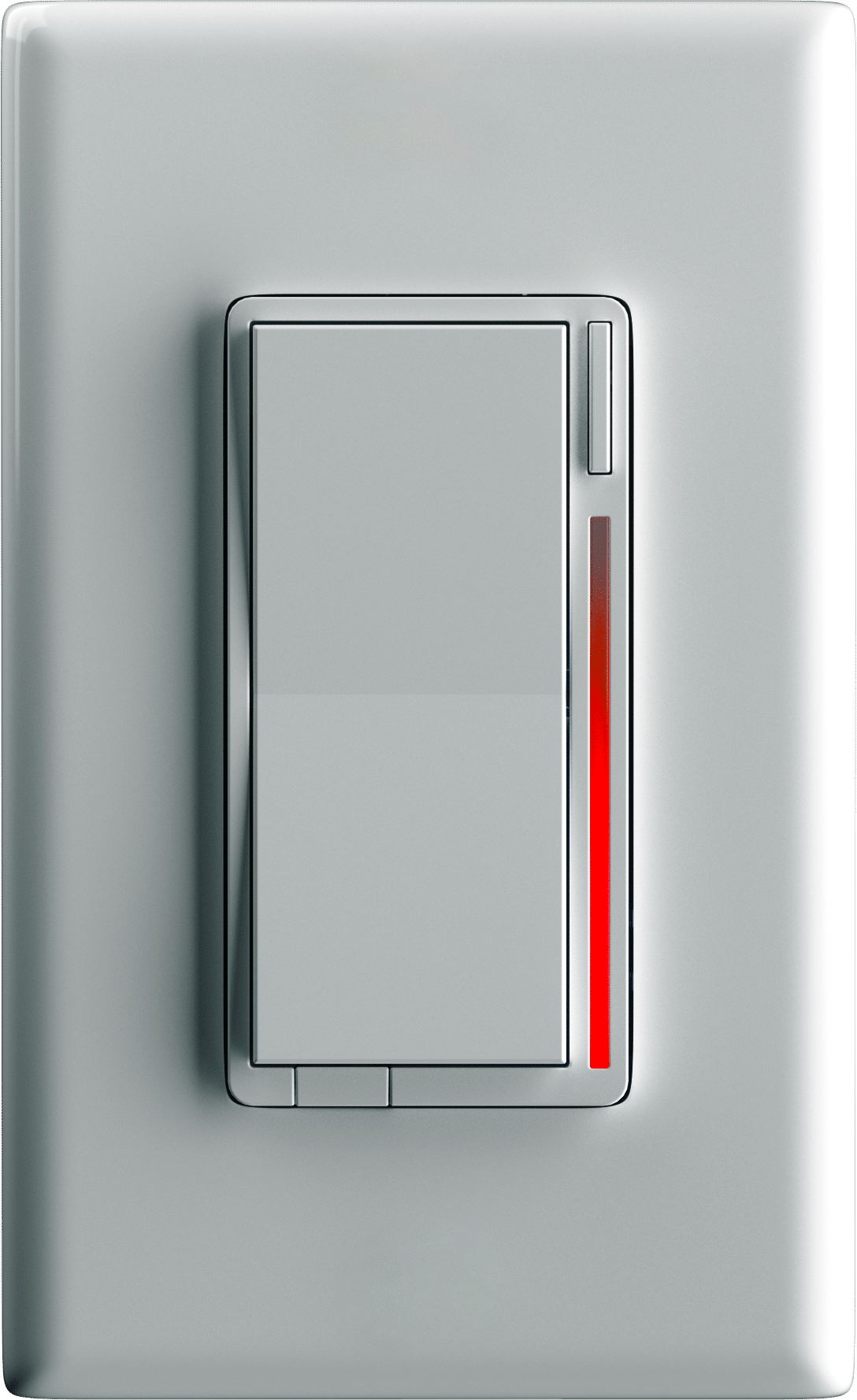
Name | Smart On/Off Switch |
|---|
Short Description | Introducing the Z-Wave® On/Off Switch with humidity detection, Multi-Tap Scene Control and LED Notifications powered by Inovelli. |
|---|
Description | The Inovelli Z-Wave® On/Off Smart Switch has a built-in humidity sensor that automatically controls lights, fans, outlets, and other general-purpose loads to keep your space comfortable and dry. Perfect for bathrooms, laundry rooms, and basements, it can kick on a fan when humidity spikes and turn things back off when the air clears. You’ll also get Inovelli’s signature LED bar for at-a-glance status and customizable notifications, plus multi-tap scene control so one switch can trigger whole-home automations, from “shower time” lighting to “goodnight” scenes. |
|---|
Brand | Inovelli |
|---|
Brand Owner | Inovelli |
|---|
Identifier | VZW30-SN |
|---|
Product Line | Red Series |
|---|
OEM Version | HW: 01 FW: 02.01 |
|---|
Hardware Platform | EFR32ZG23A |
|---|
Z-Wave Version | 7.24.2 |
|---|
Library Type | END_NODE_ENHANCED_232 |
|---|
Device Type | Multilevel Switch DT |
|---|
Role Type | ROLE_TYPE_END_NODE_ALWAYS_ON |
|---|
Manufacturer ID | 0x031E |
|---|
Product Type ID | 0x0018 |
|---|
Product ID | 0x0001 |
|---|
User Icon | 0x0600 |
|---|
Installer Icon | 0x0600 |
|---|
Radio Range Z-Wave (m) | 40 |
|---|
Radio Range Z-Wave LR (m) | 400 |
|---|
Frequency Plans | US: 916.00MHz, 908.40MHz, US_LR: 912.00MHz, 920.00MHz |
|---|
Categories | All Lighting Devices, On/Off Switches/Devices |
|---|
Countries / Regions | Canada, United States of America |
|---|
Supported Command Classes | Identifier | Name | Key | Version |
|---|
COMMAND_CLASS_ASSOCIATION_V2 | Association V2 | 0x85 | 2 | COMMAND_CLASS_ASSOCIATION_GRP_INFO_V3 | Association Group Information (AGI) V3 | 0x59 | 3 | COMMAND_CLASS_DEVICE_RESET_LOCALLY | Device Reset Locally | 0x5A | 1 | COMMAND_CLASS_FIRMWARE_UPDATE_MD_V5 | Firmware Update Meta Data V5 | 0x7A | 5 | COMMAND_CLASS_INDICATOR_V3 | Indicator V3 | 0x87 | 3 | COMMAND_CLASS_MANUFACTURER_SPECIFIC_V2 | Manufacturer Specific V2 | 0x72 | 2 | COMMAND_CLASS_MULTI_CHANNEL_ASSOCIATION_V3 | Multi Channel Association V3 | 0x8E | 3 | COMMAND_CLASS_VERSION_V3 | Version V3 | 0x86 | 3 | COMMAND_CLASS_ZWAVEPLUS_INFO_V2 | Z-Wave Plus Info V2 | 0x5E | 2 | COMMAND_CLASS_SECURITY_2 | Security 2 | 0x9F | 1 | COMMAND_CLASS_SUPERVISION | Supervision | 0x6C | 1 | COMMAND_CLASS_TRANSPORT_SERVICE_V2 | Transport Service V2 | 0x55 | 2 | COMMAND_CLASS_POWERLEVEL | Powerlevel | 0x73 | 1 | COMMAND_CLASS_SWITCH_MULTILEVEL_V4 | Multilevel Switch V4 | 0x26 | 4 | COMMAND_CLASS_BASIC_V2 | Basic V2 | 0x20 | 2 | COMMAND_CLASS_CENTRAL_SCENE_V3 | Central Scene V3 | 0x5B | 3 | COMMAND_CLASS_CONFIGURATION_V4 | Configuration V4 | 0x70 | 4 | COMMAND_CLASS_METER_V2 | Meter V2 | 0x32 | 2 | COMMAND_CLASS_SENSOR_MULTILEVEL_V11 | Multilevel Sensor V11 | 0x31 | 11 | COMMAND_CLASS_PROTECTION_V2 | Protection V2 | 0x75 | 2 | COMMAND_CLASS_SECURITY | Security 0 | 0x98 | 1 |
|
|---|
S2 Classes | S2_AUTHENTICATED, S2_UNAUTHENTICATED |
|---|
Documents | Category | File |
|---|
Manual_English | | Installer_Guide | |
|
|---|
Features | Feature | Values |
|---|
Electric Load Type | Value |
|---|
Incandescent | Fluorescent | MLV (Magnetic) | ELV (Electronic) | LED | Inductive (e.g. Motor) |
| Firmware Updatable | Value |
|---|
Updatable by Consumer by RF |
| Neutral Wire Required | | Switch Load Capacity Volt-Ampere | | Switch Load Capacity Watts | | Switch Type | Value |
|---|
Decorator Paddle Push with Indicator |
| Z-Wave Scene Type | |
|
|---|
Association Groups | Group Number | Maximum Nodes Supported | End Point ID | Group Name | Profile |
|---|
1 | 10 | 0 | Lifeline | 0x0001 | 2 | 10 | 0 | Basic Set | 0x2001 | 3 | 10 | 0 | Multilevel Set | 0x2002 | 4 | 10 | 0 | Multilevel Start/Stop | 0x2003 | 5 | 10 | 0 | Double-tap Basic Set | 0x2004 | 6 | 10 | 0 | Triple-tap Basic Set | 0x2005 | 7 | 10 | 0 | Fan Module Basic Set | 0x2006 |
|
|---|
Configuration Parameters | Parameter Number | Name | Description | Format | Size | Min Value | Max Value | Default Value |
|---|
1 | Diming Speed Up Remote | Interval of dimming: 0-100 in ms(0-10000 ms), 101-160 in seconds(1-59 seconds), 161-254 in minutes (1-93 minutes) | 1 | 1 | 0 | 0 | 0x19 | 2 | Diming Speed Up From Switch | 0-254 is the same as P1, when 255 will Keep in sync with P1 | 1 | 1 | 0 | 0 | 0xff | 3 | Ramp Rate On Remote | 0-254 is the same as P1, when 255 will Keep in sync with P1 | 1 | 1 | 0 | 0 | 0xff | 4 | Ramp Rate On From Switch | 0-254 is the same as P1, when 255 will Keep in sync with P2 | 1 | 1 | 0 | 0 | 0xff | 5 | Dimming Speed Down Remote | 0-254 is the same as P1, when 255 will Keep in sync with P1 | 1 | 1 | 0 | 0 | 0xff | 6 | Dimming Speed Down From Switch | 0-254 is the same as P1, when 255 will Keep in sync with P2 | 1 | 1 | 0 | 0 | 0xff | 7 | Ramp Rate Off Remote | 0-254 is the same as P1, when 255 will Keep in sync with P3 | 1 | 1 | 0 | 0 | 0xff | 8 | Ramp Rate Off From Switch | 0-254 is the same as P1, when 255 will Keep in sync with P4 | 1 | 1 | 0 | 0 | 0xff | 11 | Invert Switch | Invert Switch and led strip | 1 | 1 | 0 | 0 | 0x00 | 17 | LED Bar Timeout | LED Bar Timeout | 1 | 1 | 0 | 0 | 0x0b | 50 | Button Delay Time | Button Delay Time | 1 | 1 | 0 | 0 | 0x03 | 52 | Use Smart Bulb | Use Smart Bulb | 1 | 1 | 0 | 0 | 0x00 | 53 | Double Tap Up Enable | Double Tap Up Enable | 1 | 1 | 0 | 0 | 0x00 | 54 | Double Tap Down Enable | Double Tap Down Enable | 1 | 1 | 0 | 0 | 0x00 | 55 | Double Tap Up to Level | Double Tap Up to Level | 1 | 1 | 0 | 0 | 0x63 | 56 | Double Tap Down to Level | Double Tap Down to Level | 1 | 1 | 0 | 0 | 0x01 | 58 | Exclusion Behavior | Exclusion Behavior | 1 | 1 | 0 | 0 | 0x01 | 59 | Association Behavior | Association Behavior | 1 | 1 | 0 | 0 | 0x01 | 64 | LED1 Effect | LED1 Effect | 1 | 4 | 0 | 0 | 0x00000000 | 69 | LED2 Effect | LED2 Effect | 1 | 4 | 0 | 0 | 0x00000000 | 74 | LED3 Effect | LED3 Effect | 1 | 4 | 0 | 0 | 0x00000000 | 79 | LED4 Effect | LED4 Effect | 1 | 4 | 0 | 0 | 0x00000000 | 84 | LED5 Effect | LED5 Effect | 1 | 4 | 0 | 0 | 0x00000000 | 89 | LED6 Effect | LED6 Effect | 1 | 4 | 0 | 0 | 0x00000000 | 94 | LED7 Effect | LED7 Effect | 1 | 4 | 0 | 0 | 0x00000000 | 95 | LED Strip Color(On) | LED Strip Color(On) | 1 | 1 | 0 | 0 | 0xaa | 96 | LED Strip Color(Off) | LED Strip Color(Off) | 1 | 1 | 0 | 0 | 0xaa | 97 | LED Strip Intensity(On) | LED Strip Intensity(On) | 1 | 1 | 0 | 0 | 0x21 | 98 | LED Strip Intensity(Off) | LED Strip Intensity(Off) | 1 | 1 | 0 | 0 | 0x01 | 99 | LED Strip Effect | LED Strip Effect | 1 | 4 | 0 | 0 | 0x00000000 | 100 | LED Scaling | LED Scaling | 1 | 1 | 0 | 0 | 0x00 | 120 | Single Tap Handler | Single Tap Handler | 1 | 1 | 0 | 0 | 0x00 | 121 | Local Timer Status | 0-Disable,1-Enable | 1 | 1 | 0 | 0 | 0x00 | 123 | Aux Switch Scenes | Aux Switch Scenes | 1 | 1 | 0 | 0 | 0x00 | 130 | FM Control | FM Control | 1 | 1 | 0 | 0 | 0x00 | 131 | FM L Level | FM L Level | 1 | 1 | 0 | 0 | 0x19 | 132 | FM M Level | FM M Level | 1 | 1 | 0 | 0 | 0x32 | 133 | FM H Level | FM H Level | 1 | 1 | 0 | 0 | 0x63 | 134 | FM Color | FM Color | 1 | 1 | 0 | 0 | 0xff | 140 | Temperature Min Interval | Temperature Min Interval | 1 | 2 | 0 | 0 | 0x003c | 141 | Temperature Max Interval | Temperature Max Interval | 1 | 2 | 0 | 0 | 0x0e10 | 142 | Temperature Min Change | Temperature change report, unit is 0.1C | 1 | 1 | 0 | 0 | 0x05 | 143 | Humidity Min Interval | Humidity Min Interval | 1 | 2 | 0 | 0 | 0x003c | 144 | Humidity Max Interval | Humidity Max Interval | 1 | 2 | 0 | 0 | 0x0e10 | 145 | Humidity Min Change | Humidity change report | 1 | 1 | 0 | 0 | 0x03 | 158 | OnOff Dimmer Mode | 0-Dimmer, 1-OnOff | 1 | 1 | 0 | 0 | 0x01 | 159 | OnlyOneLed Mode | OnlyOneLed Mode | 1 | 1 | 0 | 0 | 0x00 | 160 | Firmware progress LED | Firmware progress LED | 1 | 1 | 0 | 0 | 0x01 | 162 | Clear Notification | Press 2x config clear notification | 1 | 1 | 0 | 0 | 0x00 | 240 | Factory Reset | Factory Reset | 1 | 4 | 0 | 0 | 0x00000000 |
|
|---|
Texts | ID | Description | Value |
|---|
8 | Where to find S2 DSK on product | The DSK information required for some inclusion methods can be found either on the product (QR Code located at the bottom front-left of the switch), or on the back of the box at the bottom left (QR Code located at the bottom right). Please keep this in a safe space or write it down for your records. | 1 | Classic Inclusion | To include (pair) your switch, start the Z-Wave inclusion process on your hub and rapidly tap the config/favorites button three times. The LED Bar will pulse blue to indicate inclusion mode and flash green if pairing is successful. | 2 | Classic Exclusion | If inclusion fails, you can reset the switch by putting your hub in exclusion mode and pressing the config/favorites button three times. The LED Bar will pulse blue and flash green if exclusion is successful, or red if not. Alternatively, hold down the top paddle and the config/favorites button simultaneously for 20 seconds until the LED Bar turns red, then release. After exclusion, you can try pairing again. | 5 | Factory Reset Procedure | To factory reset your device, first, hold the Configuration / Favorites Button followed by the up button for 20 seconds until the LED Bar (D) turns red and let go. The switch should blink red a few times indicating it has been factory reset. You may also use a certified Z-Wave controller to remove the device from your network to factory default. Only use these procedures in the event that the primary controller is missing or otherwise inoperable. |
|
|---|
Supported / Controlled Meter Types | Meter Type | Rate Type |
|---|
Electric meter | Import (consumed) |
|
|---|
Supported Multilevel Sensors | Multilevel Sensor Type |
|---|
Air temperature | Humidity |
|
|---|
Supports NWI | Yes |
|---|
Supports Explorer Frames | Yes |
|---|
Supports SmartStart | Yes |
|---|